Download
1 / 63
630 likes | 865 Vues
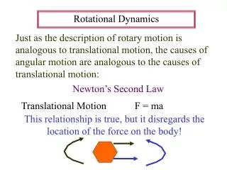
Chapter 9 Rotational dynamics. 1. Torque In this chapter we will consider only case in which the rotational axis is fixed in z direction. Fig 9-2 shows an arbitrary rigid body that is free to rotate about the z axis. *. O. P. 9-1 Torque.

E N D
1. Torque In this chapter we will consider only case in which the rotational axis is fixed in z direction. Fig 9-2 shows an arbitrary rigid body that is free to rotate about the z axis. * O P 9-1 Torque A force is applied at point P, which is located a perpendicular distance r from the axis of rotation. and lie in x-y plane, and make an angle .
The rotational quantity “torque” is defined as (9-1) The unit of torque is the Newton-meter ( ) The radial component has no effect on rotation of the body about z axis. Only the tangential component produces a rotation about the z axis. The angular acceleration also depends on the magnitude of r
When =0 ? If r=0 -that is the force is applied at or through the axis of rotation; If or , that is the force is applied in the radial direction; If =0.
Magnitude of : Direction of : using righ-hand rule * O P 2.Torque as a vector In terms of the cross product, the torque is expressed as (9-3)
Fig 9-5 shows a pendulum . The magnitude of the torque due to gravity about the point o is it has the opposite direction. Fig 9-5 Sample problem 9-1 . x mg mg
Fig 9-7 shows a single particle of mass m which is attached by a thin rod of length r and of negligible mass, and free rotates about the z axis. 9-2 Rotational inertia and Newton’s second law 1. Rotational inertia of a single particle Fig 9-7 y m r o x
A force is applied to the particle in a direction at an angle with the rod(in x-y plane). Newton’s Second law applied the tangential motion of the particle gives and , we obtain
We define to be the “rotational inertia”I of the particle about point o. (9-6) The rotational inertia depends on the mass of the particle and on the perpendicular distance between the particle and the axis of rotation.
Fig 9-8 y 0 x 2. Newton’s second law for rotation (For system of particles) y 0 x
That is (9-7) For each particle Substituting them into Eq(9-7), we obtain (9-8)
The are the same for both particles ,the total rotational inertia of this two-particle system: (9-9) The obvious extension to a rigid object consisting of N particles rotating about the same axis is (9-10)
Fig. 9-8 O y • Torque of Internal Forces: =0 0 x • Tensions and have also no torque about o. For system of particles, what kinds of force induce torque? Torque of Internal Forces is zero!!!
Thus the torque about o is due only to the external force . Thus we can rewrite the Eq(9-8) as (9-11) This is the rotational form of Newton’s Second law. Notes: , I, must be calculated about same axis. For rotations about a single axis, I is scalar. If many external forces act on the system, we add up the torques due to all the external forces about that same axis.
Three particles of masses =2.3kg, =3.2kg and =1.5kg are connected by thin rods of negligible mass, so that they lie at the vertices of 3-4-5 right triangle in the x-y plane. Fig 9-9 Sample problem 9-2 y (m) =4.5N 3 c X (m) 4
Question: • Find the rotational inertia about each of the three axes perpendicular to the x-y plane and passing through one of the particles. • A force of magnitude 4.5N is applied to m2 in the xy plane and makes an angles of 300 with the horizontal. Find the angular acceleration about oz axis. • Find the rotational inertial about an axis perpendicular to the xy plane and passing through the center of mass of the system
Solution: (a) consider first axis through Similarly for the axis through , we have For the axis through y (m) =4.5N 3 c 4 X (m)
(b) Using Eq(9-2) (c) Rotational inertial about an axis passing through the cm.
3. The parallel-axis theorem The result of the previous sample problem leads us to an important general result, the parallel-axis theorem: “The rotational inertia of any body about an arbitrary axis equals the rotational inertial about a parallel axis through the center of mass plus the total masstimesthe squared distance between two axes ”.
Fig 9-10 shows a thin slab in the x-y plane, the rotational inertia about oz is Fig 9-10 4. Proof of Parallel-Axis theorem y’ y P c X’ h o x
Substituting these transformations, we have Regrouping the terms, we can write this as
9-3 Rotational inertia of solid bodies For a rigid body which is a continuous distribution of matter. We can imagine it divided into a large number of small mass . Eq(9-10) become (9-13) Take this to the limit of infinitesimally small so that the sum becomes an integral (9-15) The integral is carried out over the entire volume of the object.
How about I of this axis 1. As an example, a rod rotates about an axis through its center. Find its rotational inertia. Fig 9-13 dx x dm Use the parallel-axis theorem
2. Another example: calculate the rotational inertia of a uniform solid rectangular about an axis perpendicular to the plate and through its center. The plate (3D) can be divided into a series of strips, each of which is to be regarded as a rod. The mass dm of the strip is axis of rotation dx x a b
The rotational inertia of the strip about the axis is Substituting for dm yields thus
1. center of gravity Imagine a body of mass M (Fig 9-18) to be divided into a large number of particles. fig 9-18 9-4 Torque due to gravity y Cg o x
Assume is a constant vector. The net torque about arbitrary axis ozdue to gravity acting on all the particles is (9-20) • The torque on the body thus equals the torque that would be produced by a single force acting at the center of mass of the body. is also the location of the “center of gravity (cg)”.
2.Center of mass (cm) and center of gravity(cg) To calculate the center of gravity, we must know not only the mass distribution of the body, but also the variation of over the body. If is not constant over the body, then the cg and cm may not coincide, because cannot be removed from the sums in eq. (9-20). If , the is the location of the “center of gravity (cg)”.
3. Find the cg Consider a body of arbitrary shape suspended from a point S (Fig 9-20). If we draw a vertical line through S, then we know that cg must lie somewhere on the line. Fig 9-20 s s c b a
Repeating the procedure with a new choice of point S as in Fig 9-20 b, we can find a second line that must contain the cg. The cg must lie at the intersection of the lines. If we suspend the object from the cg as in Fig 9-20c, and release it, the body will remain at rest no matter what its orientation.
9-5 Equilibrium applications of Newton’s law for Rotation 1.For a body to be in equilibrium both the net external force and net external torque must be zero. In this case the body will have neither an angular acceleration nor a translational acceleration. We therefore have two conditions of equilibrium: (9-22) and (9-23)
The equilibrium condition for the torques is true for any choice of the axis, when . To prove this statement,we consider Fig9-21.
In Fig 9-21, many forces act on a body, force is applied at the point located at ,force at , and so on. The net torque about an axis through o is Fig 9-21 z - o y x (9-26)
Suppose a point P is located at with respect to o. The torque about P is where for a body in translational equilibrium. Thus “the torque about any two points has the same value when the body is in translational equilibrium.”
Often we deal with problems in which all the forces lie in the same plane (x-y plane). Equilibrium condition is then (9-27) (9-28)
2.Equilibrium analysis problems Here are the procedures you should follow: 1 .Draw a boundary around the system, so that you can separate the system you are considering from its environment. 2 .Draw a free-body diagram showing all external forces that act on the system. 3 .Set up a coordinate system, resolve the forces into their components. 4 .Set up a coordinate system and axis for resolving the torque into their components.
A ladder whose length L is 12m and whose mass m is 45kg rests against a wall. Its upper end is a distance h of 9.3m above the ground, as in Fig 9-23. the cm of the ladder is one-third of the way up the ladder. A firefighter of mass M=72kg climbs halfway up the ladder. The wall is frictionless. What forces are exerted on the ladder by the wall and by the ground? Fig 9-23 Sample problem 9-7 y firefighter o x a/3 a/2
Solution: Fig 9-23 shows a free-body diagram. The wall exerts a horizontal force on the ladder. It can not exert vertical force because the wall-ladder contacts is assumed to be frictionless. The ground exerts a force with a horizontal component f due to friction and a vertical component N: the normal force.
The distance a from the wall to the foot of ladder is Using Eq(9-27) ( ),we have and
Taking torque about an axis through the point o and parallel to the z direction, then gives a negative torque, and give positive torques. Multiplying each force by its moments arm, we find (9-32)
9-6 Nonequilibrium applications of Newton’s Law for rotation In this section we will analyze problems involving angular acceleration produced by a nonzero net torque applied to an object with a fixed axis of rotation.
A playground merry-go-round is pushed by a parent who exerts a force of magnitude 115N at a point P on the rim a distance of r=1.5m from the axis. The force is exerted in a direction at an angle below the horizontal, and the horizontal component of the force is in a direction inward from the tangent at P. Fig 9-25 Sample problem 9-9 Horizontal component 1.5m tangent at P r P
(a) Find the torque . (b) Assuming that the merry-go-round can be represented as a disk 1.5m in radius and 0.40cm thick and that the child riding on it can be represented as a 0.25-kg “particle” 1m from the axis of rotation, find the resulting angular acceleration of the system.
Solution: (a) (b)
Fig 9-26 shows a pulley, which can be considered as a uniform disk of mass m=2.5kg and radius R=20cm,mounted on a fixed frictionless horizontal axis. A block of mass m=1.2kg hang from a light cord that is wrapped around the rim of the disk. Find the acceleration, tension in the cord. Fig 9-26 Sample problem 9-10 0 R T T mg
Solution: Fig 9-26 shows the system and its free-body diagram. We choose the y axis to be positive downward. We have Because the cord does not slip or stretch a must equal . Combine the equations to obtain
and We see also that the acceleration and tension depend on the mass of the disk but not the radius. As a check, we note that the formulas predict a=g and T=0 for the case of a massless disk (M=0). This is what we expect: the block simply falls as a free body.
9-7 Combined rotational and translational motion In general, an object simultaneously undergoes both rotational and translational displacements, and the translational and rotational motions may be completely independent. It has only rotational and no translational motion, or it has only translational and no rotational motion.