Download
1 / 34
340 likes | 512 Vues
The Processor: Datapath & Control. Implementing Instructions. Simplified instruction set memory-reference instructions: lw, sw arithmetic-logical instructions: add, sub, and, or, slt control flow instructions: beq (bne), j (jal) Generic implementation:

E N D
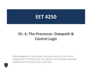
The Processor: Datapath & Control
Implementing Instructions • Simplified instruction set • memory-reference instructions: lw, sw • arithmetic-logical instructions: add, sub, and, or, slt • control flow instructions: beq (bne), j (jal) • Generic implementation: • PC to supply instruction address • get the instruction from memory • use the instruction to decide what to do • read registers • Majority of instructions use the ALU • the actions differ.
state element 1 state element 2 Combinational Logic Clocking Methodology 1/2 • Edge-triggered methodology • values stored in a sequential logic elements are updated only on clock edge • Typical execution: • read contents of state elements, • send values through some combinational logic • write results to one or more state elements
Clocking Methodology 2/2 • An edge-triggered methodology allows a state element to be read and written in the same clock cycle state element Combinational Logic
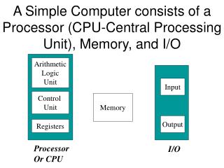
4 Add Add PC Data Reg. No Address Registers ALU Address Instruction Reg. No Instruction Memory Data Memory Reg. No Data Abstract View of Datapath • Two types of functional units: • combinational, e.g. ALU • sequential, e.g. registers
Datapath Including Control branch 4 Add Add PC Data Reg. No MemWrite Address Registers ALU Address Instruction Reg. No Instruction Memory zero Data Memory Reg. No RegWrite Data MemRead Control
Register File 5 read data 1 Read registernumber 1 32 5 Read registernumber 2 Register file Write register 5 read data 2 32 32 Write data Write
ALU Control 4 a Zero 32 ALU Result 32 Overflow b 32 CarryOut ALU Symbol & Control
4 Add PC Address Instruction Instruction Memory Instruction Fetch Instruction
op rs rt rd shamt funct 6 bits 5 bits 5 bits 5 bits 5 bits 6 bits add rd, rs, rt ALU Control 4 rs 5 32 read data 1 read register 1 Zero rt 5 Read register 2 ALU Instruction Register file 5 rd Write register read data 2 Overflow 32 32 Write data Write CarryOut R-Type Instructions
op rs rt Imm 6 bits 5 bits 5 bits 16 bits lw rt, index(rs) ALU Control Read Reg. 1 Read Data 1 MemWrite Read Reg. 2 Instruction Registers ALU Address Write Reg. Read Data 2 zero Data Memory Read Data Write Data RegWrite WriteData Sign Extend Immediate MemRead 16 32 Implementing Load & Stores rs rt rt
op rs rt Imm 6 bits 5 bits 5 bits 16 bits PC+4 Branch Target Address Shift left 2 beq rs, rt, Label Add rs ALU Control Read Reg. 1 Read Data 1 rt Read Reg. 2 Instruction Registers To Branch Control Logic ALU Write Reg. Read Data 2 zero Write Data RegWrite Sign Extend Immediate 16 32 Implementing Branches
Building the Datapath Idea: Use multiplexors to stitch them together rs rt rd Imm
Implementing Jump op Address 6 bits 26 bits j Label PC+4 [31 : 28] Jump Target Address Shift left 2 [27 : 0] 26 rs ALU Control Read Reg. 1 Read Data 1 rt Read Reg. 2 Instruction Registers ALU Write Reg. Read Data 2 Write Data RegWrite
000000 10000 10001 01000 00000 100000 rd op shamt funct rt rs Control • Control Signals • Selecting the operations to perform • Controlling the flow of data (via MUX) • Read/write enable inputs of memory and register file • Information comes from the instruction • Example: add $t0, $s0, $s1 • ALU operation is based on instruction type and function code
100101 10010 01000 0000000001100100 op address rt rs ALU Control • Example: lw $t0, 100($s2) • What should the ALU do with this instruction?
ALU Control Unit • ALU performs • addition for loads and stores • subtraction for branches (beq) • no operation for jumps • or the operation is determined by the function field for R-type instructions. • ALU Control unit will have the following inputs: • 2-bit control field called ALUOp • 6-bit function field
Main Control Unit Fields of Different Instruction Classes: 0 rs rt rd shamt funct R-type 25-21 15-11 10-6 31-26 20-16 5-0 Load or store rs rt Imm 35 or 43 25-21 31-26 20-16 15-0 2 address jump 31-26 25-0 branch rs rt Imm 4 25-21 31-26 20-16 15-0
RegDst & RegWrite load read #1 read register #1 read register #2 rt: Ins[20-16] 0 write register Register file rd: Ins[15-11] 1 write data read #1 Write RegDst R-type RegWrite
ALUSrc RegWrite read #1 read register #1 Zero read register #2 write register Register file result ALU 0 read #1 write data 1 Imm: Ins[15-0] ALUSrc signextend 16 32
MemtoReg Zero read data 1 Address 0 DataMemory write data MemtoReg From the read data 2output of Register File To the write data input of Register File
PCSrc PC Add 4 0 1 Add PCSrc Shiftleft by 2 signextend zero Imm: Ins[15-0] branch 32
Instruction RegDest ALUSrc Memto-Reg RegWrite Mem Read Mem Write Branch ALUOp1 ALUOp0 R-format 1 0 0 1 0 0 0 1 0 lw 0 1 1 1 1 0 0 0 0 sw X 1 X 0 0 1 0 0 0 beq X 0 X 0 0 0 1 0 1 Operation of the Datapath • Example Flow: beq $s0, $s1, address • The instruction is fetched from memory and PC is incremented • Read two register values • Subtract one from the other, calculate the branch address • Use the zero signal to determine which of the addresses is to be used for fetching the next instruction
state element 1 state element 2 Combinational Logic Cycle Time • The control logic is combinational • every instruction is executed in one clock cycle • Cycle time determined by length of the longest path
Single Cycle Approach • Different instructions have different execution times • Add: 3 ns • Subtract: 3.5 ns • Memory access: 10 ns • Multiplication: 20 ns • In single cycle approach, the slowest instruction determines the clock cycle time. • Another approach, divide instruction into smaller parts and execute each in a shorter clock cycle
Example • Memory access: 200 ps • ALU and addition operations: 100 ps • Register file access (read or write): 50 ps • And assume other parts (multiplexors, control units, etc) have no delay. • Instruction mix: 25% loads, 10% stores, 45% ALU ops, 15% branches, 5% jumps • Compare two approaches: single fixed clock cycle and multiple clock cycle per instruction, i.e. • what is the clock period per instruction and CPI for a fixed cycle • what is the nominal clock period and CPI for the multiple cycle approach • Execution times?