Download
1 / 37
370 likes | 501 Vues
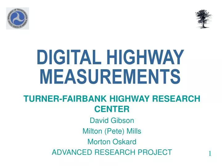
DIGITAL HIGHWAY MEASUREMENTS. TURNER-FAIRBANK HIGHWAY RESEARCH CENTER David Gibson Milton (Pete) Mills Morton Oskard ADVANCED RESEARCH PROJECT. 1. Roadside features. Vegetation. Vehicle Traffic. Contour/Terrain. Edge of Roadway. Lane Markings. Right of Way. Road Geometry.

E N D
DIGITAL HIGHWAY MEASUREMENTS TURNER-FAIRBANK HIGHWAY RESEARCH CENTER David Gibson Milton (Pete) Mills Morton Oskard ADVANCED RESEARCH PROJECT 1
Roadside features Vegetation Vehicle Traffic Contour/Terrain Edge of Roadway Lane Markings Right of Way Road Geometry Pavement Condition Long-Term Measurement Needs 2
Vision • Build a foundation to capture geometrics at required levels of accuracy not currently provided by the state of the practice • With State of the art sensors • With data fusion • With advanced analyses . • Introduce a set of highway metrics for entire right of way, (beyond simply highway geometrics) to capture health condition accurately and objectively • With State of the art sensors • With data fusion • With advanced analyses . 3
Potential Sensors • Sound Intensity Pressure Device (SIPD) • Ground Penetrating Radar (GPR) • LIDAR • Infrared Sign Retro-Reflectivity (IR) • Downward facing Camera for Pavements IR GPR SIPD 5 Camera LIDAR
Horizontal Alignment SEGMENTED APPROXIMATE PCs & PTs 7 PC = Point of Curvature, PT = Point of Tangency
Vertical Alignment DETAIL 11 MILES 8
Super-Elevation Rod and Level Data (Blue) High Accuracy INU data (Orange) Comparison with rod and level data over 2 miles 9
PennDOT Route 851: FHWA R&D Driving Simulator • Highway Geometrics for driving simulator collected in April 2004 PA Route 851 3.2 Miles 10
VDOT Application Safety Improvement West Virginia Border • Highway Geometrics for IHSDM in April 2004 • VA Route 9 From Leesburg to West Virginia Border -- 12 Miles 11 LEESBURG
Data Types • Vertical & Horizontal alignments including: PC, PT, Curve information • Super Elevation • Pavement Surface Condition • Lane Definition ( Markings and Edge ) • Roadside hardware • Linear and XYZ Referencing of data 12
Preliminary Results of Va. Rt.9 Safety Improvement Study • Algorithms modified to handle stop and go conditions • Geometry of site extracted • Segmentation of alignments in progress • Data found very repeatable • Coverage of DGPS found intermittent 13
Elevation View HEAVY FOLIAGE PROJECT ELEVATION IN FEET VALLEYS 14 PROJECT LONGITUDE IN FEET Differential GPS superimposed in blue - Arrows indicate blocked Reception
CROSS-SECTIONAL SCANS GUARD RAIL ELEVATION IN INCHES 15 OFFSET FROM CENTERLINE OF VEHICLE IN INCHES POSITION OF GUARD RAIL
Cross-Sectional Scans EDGE OF CUT ELEVATION IN INCHES 16 OFFSET FROM CENTERLINE OF VEHICLE IN INCHES CLEARANCES
Lane Attributes • LANE MARKINGS • LANE WIDTH 17
COMPARING DHM TO NDGPS AND SOP SOP (State-Of-Practice) NDGPS (National Differential GPS) Color-Coded by no. of satellites received: 3 4&5 6&789 DHM SEQUENCE OF SLIDES SHOWING CONTINUOUS HORIZONTAL ALIGNMENT DATA (1 of 9 ) 19
COMPARING DHM TO NDGPS AND SOP SEQUENCE OF SLIDES SHOWING CONTINUOUS HORIZONTAL ALIGNMENT DATA ( 7 of 9 ) 20
GPS Reception • No. of Satellites: • 3 • 4 & 5 • 6 & 7 • 8 • 9 21
SOP 22
Measuring vehicle wander in lane using DHM laser Position of vehicle in lane Pavement Markings Edge of Pavement 23
Scanning Laser + INU Pavement Markings and Edge of Pavement features fused with Trajectory 24
Multiple lanes 25 Six-Points Cross-Sections of two-lane Rural Road -- resolution = 2 feet.
Cross-Sections 26 SEQUENCE OF SLIDES SHOWING CROSS-SECTIONS
Cross-Sections 27 SEQUENCE OF SLIDES SHOWING CROSS-SECTIONS
Cross-Sections 28 SEQUENCE OF SLIDES SHOWING CROSS-SECTIONS
Visualization 29 3-D Rendering of Roadway in AUTOCAD
What is next ? • Optimize data reduction process • Reduce Data • Study Ground Truth - • Manual survey using static scanning laser • Satellite imaging using VGIN • Error & Statistical Analysis • Validation & Accuracy Report 30
Preparations for GPR Field Trial Mounting step frequency GPR hardware prior to the field trial Pavement core location - coring was carried out at selected locations in advance
Utility Detection Data – Collected Previously Manhole Horizontal slice at 18 cm depth
Utility Detection Data Power cable Horizontal slice at 110 cm depth
Utility Detection Data Collection Site Excavation Tram rails Backfill Clay Old gas pipe
Conclusion • It is possible to capture geometrics and roadway surface and structure data at high levels of accuracy using State of the art sensors, data fusion and advanced analysis procedures • These results are significantly more accurate then the state of the practice • These results would benefit from being fused with aerial surveillance data • Pooled fund study to provide one or more prototype DHM vans for use by participating states (Contact Mort.Oskard@fhwa.dot.gov) • Coordinate with Florida DOT on pooled fund studies on data.
The End ---------- Questions at Breaks