Download
1 / 18
180 likes | 344 Vues
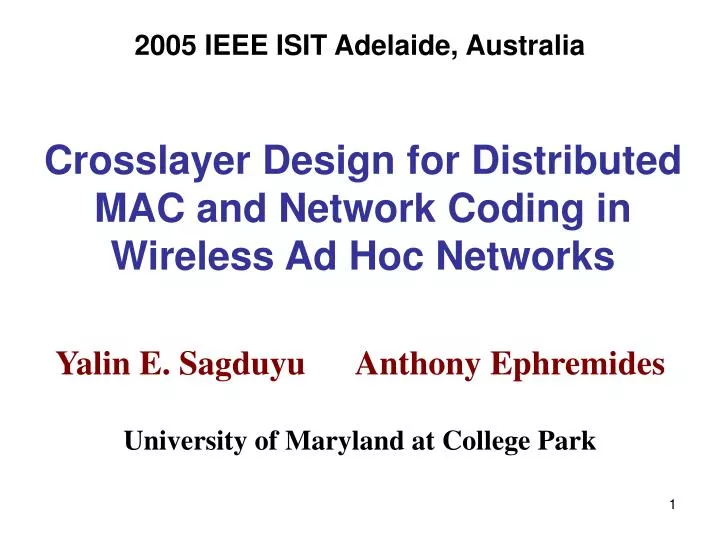
2005 IEEE ISIT Adelaide, Australia. Crosslayer Design for Distributed MAC and Network Coding in Wireless Ad Hoc Networks. Yalin E. Sagduyu Anthony Ephremides University of Maryland at College Park. Background / Motivation. Network coding was originally developed for wired networks.

E N D
2005 IEEE ISIT Adelaide, Australia Crosslayer Design for Distributed MAC and Network Coding in Wireless Ad Hoc Networks Yalin E. Sagduyu Anthony Ephremides University of Maryland at College Park
Background / Motivation • Network coding was originally developed for wired networks. • Simultaneous multiple transmissions/receptions over different links (no interference). • Throughput has been the main performance focus. • Objective: Extend network coding to operate in ad hoc wireless networks: • (1) No simultaneous transmission and reception at any node. • (2) Interference effects – need for MAC. • (3) Omnidirectional transmissions. • (4) Slotted time. • (5) Performance criteria: throughput, delay, energy-efficiency. • Joint specification of MAC and network coding is necessary. • Distributed solutions are needed for scalability.
Outline • I. Review of a Basic Method for Network Coding in a Wireless Network • Address both MAC and Network Coding. • II. Improved Joint MAC and Network Coding Methods • III. Sample Results • IV. Future Work
I. Review of a Basic Method for Network Coding s u t w y z s s s bit b1(k) b2(k+1) u u u t t t b2(k) b1(k) b2(k) b1(k) w w w b1 (k)+b2(k) b1 (k)+b2(k) z z z y y y Example of Wireless Network Coding • Source s wishes to transmit packets of two flows (1&2) to destinations y and z. • Assume classical collision channel model: • Channel Outcomes: Success, Idle, or Collision • Limited transmission/reception ranges with sharp boundaries • SINR-based model is possible as well. • Assume schedule-based interference-free MAC, i.e. conflict-free network realizations: Encoding:w computes b1+b2Decoding: 1. z computes b1+ (b1+b2) to recover b2 2. y computes b2+ (b1+b2) to recover b1
Step 1:Predetermine conflict-free wireless network realizations. I. Review of a Basic Method for Network Coding (Cont’d.) s s s t u t u t u transmitter w w w y z y z y receiver z • The problem of optimal conflict-free transmission scheduling is NP-complete. • Use a simple heuristic to construct conflict-free network realizations: One Network Realization: Adequate Set of Network Realizations: s s s t u t u u t w w w y y z y z z
I. Review of a Basic Method for Network Coding (Cont’d.) Step 2: Assign time fractions to network realizations. • Construct a hypotheticalwired network graph from the wireless network realizations: link capacity = proportion of time during which link is active 2 1 1 2 1 2 capacity of cutis 1+ 2 3 3 1 2 3 • m:time fraction assigned to the • m th network realization • A new definition of cut capacity is needed. • Choose {m, m =1,2,…} to maximizeaverage throughput per destinationor minimize • average energy cost per successfully delivered packet.
Set of wireless network realizations and hypothetical wired network graph have the same cut values and have the same maximum flows. I. Review of a Basic Method for Network Coding (Cont’d.) Step 3: Construct wireless network codes for the predetermined wireless network realizations. • Construct linear network codes for the hypothetical wired network using a polynomial- time algorithm. (e.g. S.Jaggi, P. A. Chou, K. Jain, “Low Complexity Algebraic Multicast Codes,” ISIT 2003) • Convert these wired network codesto wireless network codes such that: • Nodes accumulate the packets generated or incoming on different links over at most one schedule period. • Nodes perform the same encoding and decoding operation as determined for the hypothetical wired network; but they encode or decode only during the network realizations for which they are activated as transmitters (orreceivers).
Consider the problem of jointMAC (scheduling) and network coding. II. Improved Joint MAC and Network Coding Methods • Single common network coding method (based on subtree decomposition). (C. Fragouli, E. Soljanin, “Subtree Decomposition for Network Coding,” ISIT 2004) • Three different methods for the MAC part. • Use the results of the common network coding method to construct conflict-free transmission schedules.
II. Improved Joint MAC and Network Coding Methods (Cont’d.) Subtree Decomposition of a Network Graph • Step 1: Construct a dualline graph from the original network graph. source nodes source node s Dual Line Graph: Original Graph: su st u t ty tw uz uw w wy wz y z destination nodes destination nodes destination nodes coding nodes • Source nodes in line graph: Links in original graph that are outgoing from a source node. • Coding nodes in line graph: Links in original graph that are downstream and adjacent to more than one incoming link. • Destination nodes in line graph: Links in original graph that are incoming to a destination.
II. Improved Joint MAC and Network Coding Methods (Cont’d.) Subtree Decomposition of a Network Graph, (Cont’d.) • Step 2:Partition the dualline graph to subtrees such that 1. Each subtree contains exactly one source node OR exactly one coding node. 2. Any other node in dual graph belongs to the subtree that contains its first ancestral source or coding node. • Step 3: Construct the subtree graph from the dual line graph Dual Line Graph: Subtree Graph: source nodes T1 st su T2 ty uw uz tw T3 T4 wy wz coding nodes
II. Improved Joint MAC and Network Coding Methods (Cont’d.) Network Coding by Subtree Decomposition • Source node in the original graph generates information vector x. • y (e): symbol transmitted on link e in original graph (i.e. node e in dual line graph) • y (e) = f (e) xT , where f (e) is code vector for node e in dual line graph. • y (e) is constant for all eTi . Consider f (Ti) as the code vector for subtree Ti . • Successful decoding by destination nodes is assured if (1) The code vector of any subtree is in the linear span of code vectors of parent subtrees. (2)Thecode vectors of any two subtrees that share a destination node or that are connected to a common child subtree are linearly independent.
II. Improved Joint MAC and Network Coding Methods (Cont’d.) additional link T2 T2 T1 T1 Special Graph : Subtree Graph: T3 T4 T3 T4 Network Coding by Subtree Decomposition (Cont’d.) • Construct a special graph from subtree graph. Introduce new links between nodes, if (1) these nodes are connected to a common child node. or (2) the subtrees contain destination nodes (links in the original graph) such that these links lead to the same destination node (of original graph) • Color the special graph and assign different network codes to subtrees that have been colored with different colors. • Example: Code for T1 : [0,1] , Code for T2 : [1,0] , Codes for T3 and T4 : [1,1]
II. Improved Joint MAC and Network Coding Methods (Cont’d.) Scheduling Method A • Divide time frame into subframes and match each subframe with exactly one subtree. • Use the subtree decomposition of the network to construct conflict-free schedules. Frame Subframe 1 Subframe 2 Subtree 1 Subtree 2 Divide each subframe into three time slots. Subtree: slot 1 slot 2 slot 3 depth 0 depth 1 nodes at depth levels 0, 3, 6,… nodesat depth levels 1, 4, 7,… depth 2 nodesat depth levels 2, 5, 8, … • Divide nodes in each • subtree into three • disjoint node sets. depth 3 Nodes at depths {0,3}, 1 and 2 are separately activated. • Spatial Reuse: For a given subtree, all nodes at every third depth level can be activated simultaneously. • Choose the lengths of subframes (to either maximize throughput or minimize energy consumption per unit throughput).
II. Improved Joint MAC and Network Coding Methods (Cont’d.) Scheduling Methods B and C • Different subtrees (i.e. subframes) may include nodes that can be simultaneously activated without any conflict. • Refinement of Method A is needed: • Method B: • Determine network codes by assigning colors to subtrees. • Combine all subtrees of the same color (i.e. code) into the same subframe. • Subtrees of different colors may include nodes that can be simultaneously activated without any conflict. • Refinement of Method B is needed: • Method C: • Better spatial reuse is possible through exhaustive search for nodes that can be activated also in other subframes without any conflict.
Distributed Implementation Issues • Distributed methods should only use local exchange of information among nodes. • Questions: What amount of information is sufficient or necessary? 1. Coloring Conflict-free schedules among ordered nodes • Can be implemented by well-known distributed heuristics. 2. Subtree Construction. • Issue: For the subtree graph, we need a distributed method for the identification of the subtrees. • The existing methods are centralized and based on the availability of the global network information or global information exchange. • If the identification of the subtrees is available, then network code assignment can be implemented by well-known graph coloring heuristics. • Still, methods for coloring the subtree nodes are needed. • The aspect of distributed implementation is not finalized.
III. Network Coding vs. Plain Routing • Consider a square grid network with 9 nodes. • A randomly selected source node chooses its multicast group of size m. • Evaluate the total number of packets delivered to destination nodes per time slot. maximum improvement of network coding over routing: First Method: 28 % Scheduling Method A: 31 % Scheduling Method B: 24 % Scheduling Method C: 18 %
III. Network Coding vs. Plain Routing (Cont’d) • Consider unit energy consumption per packet transmission. • Evaluate energy consumption per successfully delivered packet to destination nodes. maximum improvement of network coding over routing: First Method: 26 % Scheduling Method A: 28 % Scheduling Method B: 22 % Scheduling Method C: 16 %
IV. Summary and Thoughts for Future Work • Addressed the problem of network coding in wireless networks. • Constructed a network coding solution over predetermined network realizations. • Presented distributed methods to derive conflict-free transmission schedules • from network codes based on subtree network decomposition. • Clearly the MAC aspect is not fully optimized. • Contention-based protocols can be partially handled through Group TDMA. • Next Problem: Network Coding for Wireless Queueing Networks. • Previous assumption: Saturated queues (for both generated packets and relay traffic). • New focus: Notion of delay or buffer overflow. • Consider network coding decisions based on queue contents.