Download
1 / 9
90 likes | 95 Vues
Learn how to define and link objects in EasySign to achieve specific plotter behaviours, such as cutting, printing, pouncing, and cutting through. Follow the steps and tips provided for efficient plotting.

E N D
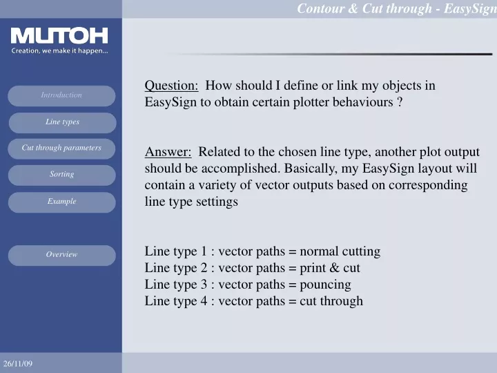
Question: How should I define or link my objects in EasySign to obtain certain plotter behaviours ? Answer: Related to the chosen line type, another plot output should be accomplished. Basically, my EasySign layout will contain a variety of vector outputs based on corresponding line type settings Line type 1 : vector paths = normal cutting Line type 2 : vector paths = print & cutLine type 3 : vector paths = pouncing Line type 4 : vector paths = cut through
What to do? Convert your line types : Normal Print & Cut Pounce Cut through
Example: 2 line typesLine 1 : Contour line Line 2 : Cut through line Cut through line contour-path
Edit - plot settings 1. Cut through parameters → cut through lines
2. Standard plot parameters → print and cut lines • Automatic sorting your line types + minimal vinyl movement • First: normal linesSecond: print & cut linesThird: pounce linesFourth: cut through lines
Due to this AUTOMATIC sorting workflow, only one alignment reading can combine multiple line typesNote: for Cut through reasons, it is better to have this dashing technique configured at the end of your vector generation> drop to ground failures of your stickers > minimal vinyl movement> speed reduction, higher force> jamming your knife tool during plotting exercises
contour-path Cut through line vector data = contour-path IN;PROGSTEP10;@SEGMENTEDFILESTART1;@SEGMENTSTART1;AL5,0,0,1,0,0,94027,133052;PA;PU0,0;PR;VS60;ZF110;PU12945,3399;PD-120,-202,-131,-196,-141,-191,-150,-183,-159,-176,-167,-168,-175,-159,-181,-150,-188,-140,-194,-130,-184,-111,-205,-112,-211,-103,-217,-92,-222,-82,-227,-71,-229,-60,-233,-49,-233,-37,-235,-25,-234,-14,-163.... UL8,10,1;LT8,11,1;VS10;ZF250;PU-65489,-9412;PD-6,-246,-17,-244,-29,-243,-40,-240,-52,-238,-62, 235,-74,-232,-85,-227,-96,-224,-106,-219,-117,-214,-12... AL5,2;@SEGMENTEND1;@SEGMENTEDFILEEND;PA;PU0,0; vector data = cut through lines
Cut through design tips: reduce your speed, increase your force, use all pressure rollers, minimal vinyl movement, 0° orientation, knife depth = cut through depth, VS/ZF/AS menu = accept, easy cut through shapes (rectangles, circles, squares, …), NO multi-frame alignment systems advised (multi-segment), NO repeat mode recommend Drag knife settings:Contour lines: 110 g, 60 cm/sCut through lines: 250 g, 10 cm/s SINGLE TOOL MODE cut through Vinyl Glue Silicon Paper