Download
1 / 40
410 likes | 589 Vues
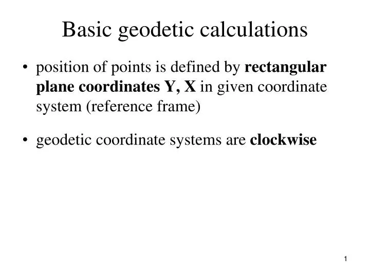
Basic geodetic calculations. position of points is defined by rectangular plane coordinates Y, X in given coordinate system (reference frame) geodetic coordinate systems are clockwise. coordinate differences x 12 = x 2 – x 1 y 12 = y 2 – y 1 x 21 = x 1 – x 2

E N D
Basic geodetic calculations • position of points is defined by rectangular plane coordinates Y, X in given coordinate system (reference frame) • geodetic coordinate systems are clockwise
coordinate differences x12 = x2 – x1 y12 = y2 – y1 x21 = x1 – x2 y21 = y1 – y2 distance s12 = s21 s12 = y12 /sin 12 s12 = x12 /cos 12
Bearing • oriented angle between parallel to the axis +X and the join of the points 21 = 12 + 180 21 = 12 + 200 gon = 12 + 200g
Given: rectangular coordinates of points P1 [y1, x1] and P2 [y2, x2], distance d13 horizontal angle 1 Calculated: P3 [y3, x3] Determination of a point defined by polar coordinates (bearing and distance)
according to the table12 13 = 12 + 1 Coordinate differences: y13 = d13 . sin 13 x13 = d13 . cos 13 y3 = y1+ y13 = y1 + d13 . sin 13 x3 = x1+ x13= x1 + d13 . cos 13
Given: rectangular coordinates of points P1 [y1, x1] and P2 [y2, x2], horizontal angles 1 a 2 Calculated: P3 [y3, x3] Calculation of the coordinates by intersection from angles
according to the table12 21 = 12 + 200 gon s13 = s12 . sin 2 / sin (200 gon – (1 + 2)) = s12 . sin 2 / sin (1 + 2) , s23 = s12 . sin 1 / sin (200 gon – (1 + 2)) = s12 . sin 1 / sin (1 + 2) (law of sines)
13 = 12 + 1 23 = 21 – 2 y3 = y1 + s13 . sin 13 = y2 + s23 . sin 23 x3 = x1 + s13 . cos 13 = x2 + s23 . cos 23 Coordinates of the point P3 are determined twice using bearings and distances to check the calculation.
Intersection from distances Given: rectangular coordinates of points P1 [y1, x1] and P2 [y2, x2], measured horizontal distances d13 a d23 Calculated: rectangular coordinates of P3 [y3, x3]
13 = 12 + 1 23 = 21 – 2 y3 = y1 + s13 . sin 13 = y2 + s23 . sin 23 x3 = x1 + s13 . cos 13 = x2 + s23 . cos 23 Coordinates of the point P3 are determined twice using bearings and distances to check the calculation.
Resection Given: rectangular coordinates of points P1 [y1, x1], P2 [y2, x2], P3 [y3, x3] measured horizontal angles 1 a 2 Calculated: rectangular coordinates of P4 [y4, x4]
Traverse (polygon) • a broken line connecting two survey points • traverse points = vertexes of the broken line • traverse legs = joins of nearby traverse points • horizontal angles at all traverse points and lengths of traverse legs are measured • coordinates Y, X of the traverse points are calculated
Traverse • connected (at one or both ends) – the traverse is connected to the survey points whose coordinates are known • disconnected – the traverse is connected to the survey points whose coordinates are not known Dividing traverses according to a shape: • traverse line • closedtraverse – the start point = the end point Orientation of a traverse = measurement of the horizontal angle at the start (or the end) point.
Given: coordinates of the start and the end points 1 [y1, x1], n [yn, xn] (here n = 5) coordinates of the orientation points A [yA, xA], B [yB, xB] measured horizontal distances d12, d23, d34, d45 measured horizontal angles ω1, ω2, ω3, ω4, ω5 Calculated: coordinates of points 2 [y2, x2], 3 [y3, x3], …, n-1 [yn-1, xn-1]
calculation of bearings according to the table 1A and nB
2. angular adjustment Angular error Oω is calculated (error = „it should be“ minus „it is“. „It should be“ is the bearing nB calculated from coordinates, „it is“ is the bearing αnB calculated using measured horizontal angles). i = 1, … , n n … number of the traverse points (here n = 5)
Clause for the angular adjustment: The angular error is divided equally to the measured horizontal angles: = O / n ´1 = 1 + , ... , ´n = n + .
3.calculation of bearings 12 = 1A + ´1 23 = 12 + ´2 ± 200g … n-1,n = n-2,n-1 + ´n-1 ± 200g nB = n-1,n + ´n ± 200g = nB Check!
4.calculation of coordinate differences y12 = d12 . sin 12 … yn-1,n = dn-1,n . sin n-1,n x12 = d12 . cos 12 … xn-1,n = dn-1,n . cos n-1,n
5. calculation of coordinate deviations y1n = yn – y1 x1n = xn – x1 y1ncal = y12 + y23+ y34 + y4n = y x1ncal = x12 + x23+ x34 + x4n= x Oy = y1n–y Ox = x1n–x
Positional difference Clause for the adjustment:
Corrections of coordinate differences The corrections of coordinate differences are not equal, they depend on values of coordinate differences.
6. corrected coordinate differences … Check!
7. calculation of adjusted coordinates y1 = given x1 = given y2 = y1 + y´12 x2 = x1 + x´12 …. yn = yn - 1 + y´n – 1, n = given Check! xn = xn - 1 + x´n – 1, n = given Check!
Given: measured horizontal distances d12, d23, d34, d41 measured horizontal angles ω1, ω2, ω3, ω4 Calculated: coordinates of points P1 [y1, x1], P2 [y2, x2], P3 [y3, x3], P4 [y4, x4]
1. choice of a local coordinate system One of the traverse points is chosen as a beginning of a local coordinate system (here P1) and one axis is put in the traverse leg from this point (here axis +Y is put in P1P2). Coordinates of the beginning are chosen, usually: y1 = 0,00, x1 = 0,00 Result from this choice: x2 = 0,00, 12 = 100g
The calculation is the same as previous one, the start point = the end point = P1. 2. angular adjustments i = 1, … , n n … number of the traverse points (here n = 4)
Clause for the angular adjustment: Angular error is divided equally to the measured horizontal angles: = O / n ´1 = 1 + , ... , ´n = n + .
3. calculation of bearings 12 = 12 = 100g 23 = 12 + ´2 ± 200g … 41 = 34 + ´4 ± 200g 12 = 41 + ´1 ± 200g = 12 Check!
4. calculation of coordinate differences y12 = d12 . sin 12 … y41 = d41 . sin 41 x12 = d12 . cos 12 … x41 = d41 . cos 41
5. calculation of coordinate deviations y1n = yn – y1= 0 x1n = xn – x1= 0 y1ncal = y12 + y23+ y34 + y4n = y x1ncal = x12 + x23+ x34 + x4n= x Oy = –y Ox = –x
Positional difference Clause for the adjustment:
6. corrected coordinate differences …. Check!
7. calculation of adjusted coordinates y1 = given x1 = given y2 = y1 + y´12 x2 = x1 + x´12 …. y1 = y4 + y´41 = given Check! x1 = x4 + x´41 = given Check!