Download

1 / 47
470 likes | 637 Vues
An Analytic Model of Hierarchical Mass Storage Systems with Network-Attached Storage Devices. Daniel A. Menasce, Dept. of C.S. of GMU Odysseas I. Pentakalos, Dept. of C.S. and E.E.of UMBC Yelena Yesha, Dept. of C.S. and E.E.of UMBC. Abstract.

E N D
An Analytic Model of Hierarchical Mass Storage Systems with Network-Attached Storage Devices Daniel A. Menasce, Dept. of C.S. of GMU Odysseas I. Pentakalos, Dept. of C.S. and E.E.of UMBC Yelena Yesha, Dept. of C.S. and E.E.of UMBC
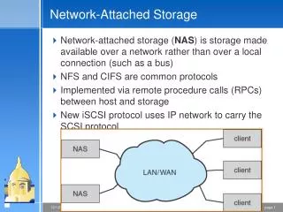
Abstract • This paper shows how queuing network models can be used to assess the performance of hierarchical mass storage systems that use network attached storage devices. • It improves I/O performance by separating control and data paths and eliminating host intervention during data transfer. • Devices are attached to a high speed network for data transfer and to a slower network for control messages. • Hierarchical mass storage systems use disks to cache the most recently used files and tapes to store the bulk of the files in the file system.
Introduction • Problem: • Most current mass storage systems are based on the server attached storage model in which all storage devices are attached to a single machine using high speed buses and I/O channels. • As the arrival rate of requests increases, the server may become a bottleneck since all data needs to flow through its main memory. • Solution: • Network attached storage has been emerging in the design of mass storage system hierarchies. It makes storage devices directly attached to the network.
Hierarchical Mass Storage Systems • The two main operations on a mass storage system are file storage (put) and retrieval (get). • Files stored in the mass storage system are placed on the disk cache and migrate to the tapes if they are not used for some specified time. • A get may be satisfied from the disk cache (a cache hit) or from the tape via the disk cache (a cache miss).
Architecture of a NAD • Clients issue gets and puts through the SACN. The File Server controls the operation of the NADs through the SUCN. Finally, data flows between the File Server and a NAD through the High Speed Data Network. • Normally, the SACN and the SUCN are the same Ethernet network, whereas the High Speed Data Network is a point-to-point HIPPI connection.
HIPPI and IPI-3 Protocols • HIPPI (High Performance Parallel Interface) is a simplex point-to-point interface with a data transfer rate of 800 Mbit/sec and 1600 Mbit/sec based on a 32 and 64 bit word size, respectively. • Before data can be transferred, the source must first establish a connection with the destination by placing the address of the destination on the bus. • Once the connection has been established, a packet of data can be transferred in the form of multiple bursts. The source indicates that it is ready to transfer a burst and the destination must send an acknowledgement, thus allowing for flow control. • After all data is transferred, the connection is broken. • Note that a file transfer over a HIPPI switch may imply many rounds of connect, transfer, and disconnect.
The HIPPI Frame • The HIPPI frame includes two data fields D1 and D2: • D1 is intended for transferring user control information. • By limiting the size of the header plus the D1 area to 1024 bytes, the command can be transferred to the destination within the first burst and be delivered and processed while the data stored within the D2 area is still being transferred using additional bursts.
The Intelligent Peripheral Interface (IPI-3) • The Intelligent Peripheral Interface is a device independent protocol which defines a generic command set for data transfer to and from magnetic and optical disk drives, allowing vendors to use a single device driver for communicating with a number of devices.
Transfer Protocols • Three protocols are based on whether the transfer is device-to-client or device-to-device and whether it is source or sink initiated. • A device-to-client protocol is used when data is transferred from the File Server (a client) to a NA Disk device, whereas a device-to-device protocol is used when the transfer is from a NA Disk device to a NA Tape device. • In all protocols the control messages are sent over the Storage Unit Control Network (SUCN) while the data transfer messages are sent over the High Speed Data Network (HSDN).
Some Abbreviations • FS : File Server • FSDM : File Server Disk Mover • NADM : NA Disk Mover • NATM : NA Tape Mover
Read from a NA Disk to the File Server. 1. A user sends a read request to the FS over the SUCN. 2. The FS processes and forwards the request to the NADM over the SUCN. 3. The NADM prepares for the move, assigns a TID that the FSDM will use to identify the transfer, and sends a response back to the FS over the SUCN containing the TID assigned. 4. The FS sends an IPI third-party read request to the FSDM.
Read from a NA Disk to the File Server(Continued) 5. The FSDM prepares for the move and then sends an IPI-3 read command message within the D1 area of the HIPPI frame over the HIPPI channel. 6. The NADM when ready, sends an IPI-3 response within a HIPPI frame. The D1 area contains the transfer notification message and the D2 area contains a data block. 7. Once the file has been transferred, both movers send completion messages back to the FS. Note: Steps 5 and 6 are repeated for each block until all the data has been sent.
Write from the File Server to an NA Disk Note: Files are always stored in the disk cache first. 1. A user sends a write request to the FS over the SUCN. 2. The FS processes and forwards the request to the FSDM. 3. The FSDM prepares for the move, assigns a TID that will be used to identify the transfer, and sends a response back to the FS.
Write from the File Server to an NA Disk(Continued) 4. The FS sends a write request to the NADM over the SUCN indicating the direction of data flow, the amount of data to be transferred, the TID to be used to identify the transfer. 5. The NADM prepares for the move and sends an IPI-3 read command message within the D1 area of the HIPPI frame over the HIPPI channel. 6. The FSDM, when ready, sends an IPI-3 response within an HIPPI frame. The D1 area contains the transfer notification message and the D2 area contains a data block. 7. Once the file has been transferred, both movers send completion messages back to the FS.
Read from a NA Tape to a NA Disk 1. A user sends a read request to the FS over the SUCN for a file stored in a tape device. 2. The FS processes and forwards the request to the NATM over the SUCN. 3. The NATM prepares for the move, assigns a TID that the NADM will use to identify the transfer, and sends a response back to the FS over the SUCN.
Read from a NA Tape to a NA Disk(Continued) 4. The FS sends a request, which indicates the direction of data flow and the TID, to the NADM over the SUCN. 5. The NADM sends an IPI-3 read command to the NATM over the HIPPI channel. 6. The NATM, when ready to transmit a block, sends the block of data in an IPI-3 response with the transfer notification message in the D1 area and the data block in the D2 area. 7. Both movers send completion messages back to the FS over the SUCN.
3. NAD Performance Model • Characteristics of the workload • QN model • Equations used to compute the service demand parameters • Model to handle tape to disk transfers
3.1 Workload characterization • FTP get/put request log for ten days to get the histogram. • K-means clustering algorithm was used to determine the appropriate number of classes for get/put requests and average file size for each class.
3.2 QN Model • Performance model consists of a closed multiple class QN with load dependent devices. • User workstations are represented by a delay center which model the user think time • SACN/SUCN are assumed to be implemented by Ethernet—a load dependent device since its service rate depends on the load imposed on it.
QN Model (continued..) • File Server is modeled by a CPU and a host-attached disk device. • HIPPI is represented by a queuing device. • NA server(NA disk/tape) is represented by two queuing devices:one is cpu where mover OS and local file system runs; the other is the actual NA device
3.3 Input parameters • Based on FTP log, we can get the think time Zc.
3.4 Computation of Service Demands • This section describes the equations used to compute the service demands for each device of the QN model using the parameter described in 3.3 • Dws = Zc (think time) • Dlan,c(service demand for class c at Ethernet) depends on the class and on the hit ratio ph.
LAN service demand For c {g1,g2,g3,g4} • Nframesd is the # of frames transmitted when the request is serviced by NA disk (disk cache hit):By inspecting the protocols in 2.2,one request frame,two setup frame and one completion indication frame. So Nframesd=4 • Nframest = 9 • For put request, files are always written to the disk cache. It’s not dependent on Ph. • Nframesw = 3 For c {p1,p2,p3,p4}
HIPPI service demand For c {g1,g2,g3,g4} • (1) is the portion of the service demand due to transfer from the NA disk to file server HA disk(cache hit) • (2) is the portion of the service demand due to a transfer from a NA tape read/write station to a NA disk (in the case of disk cache miss) • For put, files are always written to the disk cache. It does not depend on the hit ratio of the NA disk. (1) (2) For c {p1,p2,p3,p4}
CPU service demand For all class c: • Notice that the hit ratio does not affect the part of the equation that depends on the file size since , in the case of a disk cache miss, the NA tape to NA disk transfer is a device to device transfer and does not impose any load on the CPU of the file server. ?
HA disk service demand For all class c: • Notice that the hit ratio does not affect the part of the equation that depends on the file size since , in the case of a disk cache miss, the NA tape to NA disk transfer is a device to device transfer and does not impose any load on the HA disk of the file server. • (1) gives the average time spent in seek and latency per block read/written for class c files. We assume that first block will require and average seek and an average latency while the remaining blocks will require a seek and latency with probability Psl(assumed to be 0.1) (1)
NA disk mover service demand For c {g1,g2,g3,g4} • The service demand for NA disk mover depends only on the class of the request. If the read request is a hit at the NA disk cache, then only one transfer takes place whereas on a miss the file goes from the NA tap to the NA disk and from NA disk to HA disk. • Put request involves a single transfer by the NADM For c {p1,p2,p3,p4}
NA disk server service demand For c {g1,g2,g3,g4} • The service demand for NA disk server depends both on the request class and disk cache hit ratio. • Assuming that requests are equally likely to use any of the Nd disks of the NA disk server. • The factor 2 in (2) comes from the fact that a miss requires both an NA tap to NA disk and an NA disk to HA disk transfer. • Put request always requires a transfer from the HA disk to NA disk For c {p1,p2,p3,p4}
NA tape mover service demand For c {g1,g2,g3,g4} • The service demand for NA tape mover depends both on the class of the request and on the hit ratio. • A get request arrives at the NA tape mover only if the file is not located at the NA disk cache. • For put request, its request demand is zero, since puts never go explicitly to the NA tape device. For c {p1,p2,p3,p4} D NATM,c = 0
NA tape device service demand For c {g1,g2,g3,g4} • The service demand for NA tape device depends both on the class of the request and on the hit ratio. • A get request arrives at the NA tape mover only if the file is not located at the NA disk cache. • For put request, its request demand is zero, since puts never go explicitly to the NA tape device. For c {p1,p2,p3,p4} D NAT,c = 0
Modeling Tape to Disk Transfer • File transfer from NA tape to NA disk exhibits simultaneous resource possession since once a tape is mounted for a tape to disk transfer,the tape read/write station cannot be used for any other transfer until all blocks of the file have been transferred. So a file transfer request holds tape read/write station and the HIPPI switch or the disk. • The residence time at the tape is equal to the effective service demand at tape plus the waiting time to acquire the tape drive for the first time. • The effective service demand at tape is defined as the sum of the actual service demand at the tape DNAT plus disk service demand, plus total waiting time at disk for all blocks, plus the service demand and waiting time at HIPPI switch.
NA tape residence time For c {g1,g2,g3,g4} Residence time of class c requests at a NA disk due to tape to disk transfers generated by disk cache misses Residence time of class c requests at HIPPI switch due to tape to disk transfers generated by disk cache misses
Simulation Condition • 1 file server with 4 disk • 1 NA disk server with 96 disk • 4 NA tape server with 6 tape drive • 1 user workstation • 1 HIPPI switch • 1 LAN network
2 1 3 1 2 1 2 3 No role HA disk HA disk HA disk NA disk NA disk NA disk NA tape NA tape NA tape Analysis (Bottleneck) Small Ph Ph>0.7 Ph=1.0
Get Request Analysis (Congestion factor cf) • Definition: cf = (residence time)/ (service demand) • Cf at HA disk increase with Ph • Cf at NA tape decrease with Ph • Cf at NA disk increase until Ph=0.6 and decrease.
Put Request Analysis (Congestion factor cf) • Cf has similar behavior for HA and NA disk • Cf at HA disk increase with Ph • Cf at NA disk increase until Ph=0.6 and decrease. • After Ph=0.6 the decrease is unable to offset the increase. I.E. transfer time always increase for put class
Get Request Analysis • Definition of load factor: the maximum number of outstanding request • Hit ratio = 0.3 (reasonable small) • Most get needs to go to NA tape. Smaller file tend to queue at NA tape behind large file since the tape has to be allocated to a single request for the entire duration of transfer
Put Request Analysis • Put request does not use NA tape • The transfer time is largely influenced by the congestion at NA disk
Varying the Number of NA server disk Hit ratio = 0.3 Load factor = 15
Analysis for g3 and g4 • The bottleneck is NA disk. • From 1 NA disk to 2 NA disks • The percentage of time spent at NA disk drops significantly • The percentage of time spent at NA tape increases significantly • The influence of Item 2 is less than the influence of item 1. I.E. the total transfer time decrease • From 2 disks beyond, stay constant
Analysis for g1 and g2 • The bottleneck is NA tape. • From 1 NA disk to 2 NA disks • Aggravate the bottleneck • Increase the transfer time • From 2 beyond, the bottleneck shifts to HA disk. The transfer time does not change any more.
Conclusion • Model based on approximation to standard multiclass MVA • Deals with simultaneous resource possession that occurs when files are transferred between network-attached tapes to network-attached disk across HIPPI switch • Validated with simulation and be accurate at 10% • Analysis on the relationship of the transfer time with disk cache hit ratio, system load, and number of network-attached disks