Download
1 / 24
250 likes | 363 Vues
Lecture 8: Capacitors and PN Junctions. Prof. Niknejad. Lecture Outline. Review of Electrostatics IC MIM Capacitors Non-Linear Capacitors PN Junctions Thermal Equilibrium. +++++++++++++++++++++. − − − − − − − − − − − − − − −. Electrostatics Review (1).

E N D
Lecture 8: Capacitors and PN Junctions Prof. Niknejad
Lecture Outline • Review of Electrostatics • IC MIM Capacitors • Non-Linear Capacitors • PN Junctions Thermal Equilibrium University of California, Berkeley
+++++++++++++++++++++ − − − − − − − − − − − − − − − Electrostatics Review (1) • Electric field go from positive charge to negative charge (by convention) • Electric field lines diverge on charge • In words, if the electric field changes magnitude, there has to be charge involved! • Result: In a charge free region, the electric field must be constant! University of California, Berkeley
+++++++++++++++++++++ − − − − − − − − − − − − − − − Electrostatics Review (2) • Gauss’ Law equivalently says that if there is a net electric field leaving a region, there has to be positive charge in that region: Electric Fields are Leaving This Box! Recall: University of California, Berkeley
Electrostatics in 1D • Everything simplifies in 1-D • Consider a uniform charge distribution Zero field boundary condition University of California, Berkeley
Electrostatic Potential • The electric field (force) is related to the potential (energy): • Negative sign says that field lines go from high potential points to lower potential points (negative slope) • Note: An electron should “float” to a high potential point: University of California, Berkeley
More Potential • Integrating this basic relation, we have that the potential is the integral of the field: • In 1D, this is a simple integral: • Going the other way, we have Poisson’s equation in 1D: University of California, Berkeley
Boundary Conditions • Potential must be a continuous function. If not, the fields (forces) would be infinite • Electric fields need not be continuous. We have already seen that the electric fields diverge on charges. In fact, across an interface we have: • Field discontiuity implies charge density at surface! University of California, Berkeley
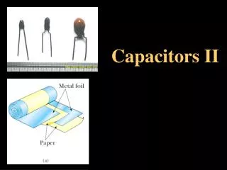
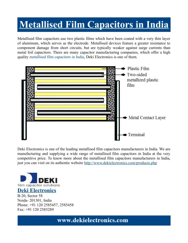
Top Plate Bottom Plate Bottom Plate Thin Oxide IC MIM Capacitor • By forming a thin oxide and metal (or polysilicon) plates, a capacitor is formed • Contacts are made to top and bottom plate • Parasitic capacitance exists between bottom plate and substrate Contacts University of California, Berkeley
Vs + − Review of Capacitors • For an ideal metal, all charge must be at surface • Gauss’ law: Surface integral of electric field over closed surface equals charge inside volume +++++++++++++++++++++ − − − − − − − − − − − − − − − University of California, Berkeley
+++++++++++++++++++++ − − − − − − − − − − − − − − − Capacitor Q-V Relation • Total charge is linearly related to voltage • Charge density is a delta function at surface (for perfect metals) University of California, Berkeley
+++++++++++++++++++++ − − − − − − − − − − − − − − − A Non-Linear Capacitor • We’ll soon meet capacitors that have a non-linear Q-V relationship • If plates are not ideal metal, the charge density can penetrate into surface University of California, Berkeley
What’s the Capacitance? • For a non-linear capacitor, we have • We can’t identify a capacitance • Imagine we apply a small signal on top of a bias voltage: • The incremental charge is therefore: Constant charge University of California, Berkeley
Small Signal Capacitance • Break the equation for total charge into two terms: Incremental Charge Constant Charge University of California, Berkeley
Example of Non-Linear Capacitor • Next lecture we’ll see that for a PN junction, the charge is a function of the reverse bias: • Small signal capacitance: Voltage Across NP Junction Charge At N Side of Junction Constants University of California, Berkeley
Carrier Concentration and Potential • In thermal equilibrium, there are no external fields and we thus expect the electron and hole current densities to be zero: University of California, Berkeley
Carrier Concentration and Potential (2) • We have an equation relating the potential to the carrier concentration • If we integrate the above equation we have • We define the potential reference to be intrinsic Si: University of California, Berkeley
Carrier Concentration Versus Potential • The carrier concentration is thus a function of potential • Check that for zero potential, we have intrinsic carrier concentration (reference). • If we do a similar calculation for holes, we arrive at a similar equation • Note that the law of mass action is upheld University of California, Berkeley
The Doping Changes Potential • Due to the log nature of the potential, the potential changes linearly for exponential increase in doping: • Quick calculation aid: For a p-type concentration of 1016 cm-3, the potential is -360 mV • N-type materials have a positive potential with respect to intrinsic Si University of California, Berkeley
p-type NA ND n-type PN Junctions: Overview • The most important device is a junction between a p-type region and an n-type region • When the junction is first formed, due to the concentration gradient, mobile charges transfer near junction • Electrons leave n-type region and holes leave p-type region • These mobile carriers become minority carriers in new region (can’t penetrate far due to recombination) • Due to charge transfer, a voltage difference occurs between regions • This creates a field at the junction that causes drift currents to oppose the diffusion current • In thermal equilibrium, drift current and diffusion must balance − V + + + + + + − − − − − − − − − − − − + + + + + + + + + + − − − − − − University of California, Berkeley
PN Junction Currents • Consider the PN junction in thermal equilibrium • Again, the currents have to be zero, so we have University of California, Berkeley
p-type n-type ND NA – – + + Transition Region PN Junction Fields University of California, Berkeley
Total Charge in Transition Region • To solve for the electric fields, we need to write down the charge density in the transition region: • In the p-side of the junction, there are very few electrons and only acceptors: • Since the hole concentration is decreasing on the p-side, the net charge is negative: University of California, Berkeley
Charge on N-Side • Analogous to the p-side, the charge on the n-side is given by: • The net charge here is positive since: – – + + Transition Region University of California, Berkeley