Download
1 / 19
300 likes | 971 Vues
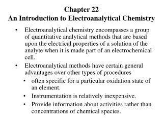
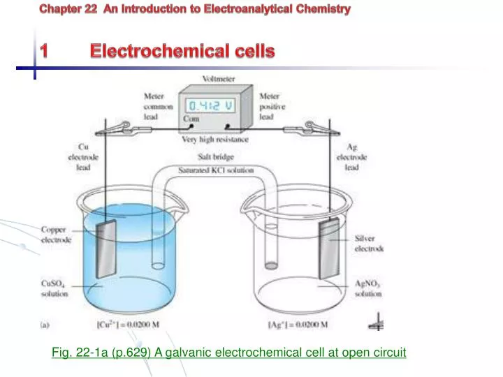
Chapter 22 An Introduction to Electroanalytical Chemistry 1 Electrochemical cells. Fig. 22-1a (p.629) A galvanic electrochemical cell at open circuit. 1.1 components Conducting electrodes (metal, carbon) External wires (electrons carry current)

E N D
Chapter 22 An Introduction to Electroanalytical Chemistry1 Electrochemical cells Fig. 22-1a (p.629) A galvanic electrochemical cell at open circuit
1.1 components • Conducting electrodes (metal, carbon) • External wires (electrons carry current) • Ion electrolyte solution (ions carry current) • Interfaces or junctions • Complete electrical circuit conduction: electrons moving from one electrode to another thru. External wire within solutions, migration of ions carry current at electrode surface, oxidation or reduction reactions occur coupling the electron conduction of electrodes w/ ion conduction of solutions
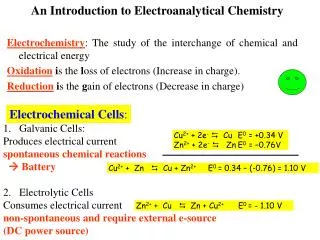
1.2 Galvanic Cells – cell develops spontaneous potential difference Overall: 2Ag+(aq) + Cu(s) 2Ag(s) + Cu2+(aq) Half reactions: Cu(s) Cu2+ (aq) + 2e- Oxidation Ag+ + e- Ag (s) Reduction Convention: Cathode where reduction occurs Anode where oxidation occurs Galvanic cell: Cu anode (negative) Ag cathode (positive) Cu2+ = 0.02 M, Ag+ = 0.02 M, E = 0.412 V 0 V reaction equilibrium Potential difference (voltage) is measure of tendency to move to equilibrium
1.3 electrolytic cells – require potential difference greater than galvanic potential difference ( to drive away from equilibrium) Overall: 2Ag(s) + Cu2+(aq) 2Ag+(aq) + Cu(s) [chemically reversible cell] Half reactions: Ag(s) Ag+ (aq) + 2e- Oxidation Cu2+(aq) + 2e- Cu(s) Reduction electrolytic cell: Ag anode (negative) Cu cathode (positive)
1.4 Cell w/o liquid junctions AgCl(s) Ag+ (aq) + Cl- (aq) H2 (g) H2 (aq) Cathode: AgCl(s) Ag+ + Cl- Ag+ + e- Ag (s)- Anode: H2 (aq) 2H+ (aq) + 2e- Overall: 2AgCl (s) + H2(g) 2Ag(s) + 2H+ + 2Cl- direct reaction of AgCl + H2 is very slow
1.5 Schematic representation of cells Short-hand cell notation Cu|CuSO4(Cu2+ = 0.0200) ||AgNO3 (Ag+ = 0.0200)| Ag | liquid-electrode interface || two phase boundaries, one at each end of the salt bridge convention: anode on left Galvanic cell as written Electrolytic cell if reversed Pt, H2 (p=1atm)|H+ (0.01M), Cl-(0.01M), AgCl (sat’d) | Ag
2 Electrode Potentials 2.1 Cell potential (difference between anode and cathode potential) Ecell = Ecathode – Eanode when half-reactions written as reduction (electron on left) Example: 2AgCl(s) + H2(g) 2Ag (s) + 2H+ + 2Cl- Cathode: 2AgCl(s) + 2e- 2Ag (s) + 2Cl- Anode: 2H+ + 2e- H2(g) Galvanic cell Ecell = Ecathode – Eanode = EAgCl/Ag – EH+/H2 = +0.46 V Can’t measure potential on each electrode independently – only differences
2.2 Standard reference electrode Standard hydrogen electrode (SHE) Pt, H2(p=1.00atm) | H+ (H+ = 1.00M)||… • SHE assigned 0.000V • can be cathode or anode {depending on the half cell which it couples with} - Pt does not take part in reaction, coated with a finely divided layer of platinum to provide large surface area • controlled activity of reactants • rarely used for routine measurement
Fig. 22-5 (p.637) measurement of the electrode potential for M electrode
Alternative references electrodes {which are simple to prepare} a. Calomel electrode Hg|Hg2Cl2(sat’d), KCl(xM)|| Hg2Cl2 (s) + 2e- 2Cl- + 2Hg (l) Ereference depends on Cl-1 Ereference = +0.24V vs. SHE for saturated calomel electrode (SCE)
b. Silver-silver chloride electrode Ag|AgCl(sat’d), KCl(xM)|| AgCl(s) + e- Cl- + Ag (s) - Similar construction to calomel electrode Ag wire coated with AgCl Solution of KCl sat’d with AgCl - Again, Ereference depends on Cl-, and = + 0.22 V vs. SHE - Can be used for uncontrolled temperature (lower temperature coefficient, see Table 23-1) Can be used for temp > 60C - But Ag reacts with more ions (e.g, proteins), while Hg reacts with few sample components,
Fig. 23-2 (p.661) Typical commerical reference electrode a) A saturated calomel electrode, and b) a silver-silver chloride electrode
2.3 electrode and standard electrode potential (E and E0) - Definition: potential of electrodes vs. SHE - Electrode potential varies with activity of ion Activity x = x[X] x: activity coefficient, varies with presence of other ions (ionic strength) (see Appendix 2) Note: activity of pure liquid or solid in excess = 1.00 Use pressure (atm) for gases If = 1.00M, the electrode potential E, becomes standard electrode potential E0 Appendix 3 Cu2+ + 2e- Cu(s) E0 = +0.337 V 2H2+ + 2e- H2(g) E0 = +0.000 V Cd2+ + 2e- Cd(s) E0 = - 0.403 V Zn2+ + 2e- Zn(s) E0 = -0.763 V
2.4 Nernst equation In general, E and Ecell can be calculated for any activity using Nernst equation: pP + qQ + ne- rR + sS E = E0 when log quotient is unity E0 is relative to SHE E0 is measure of driving force for half-cell reduction
3. Electrical double layer* electrons transferred at electrode surface by redox reactions, occurring at solution/electrode interface Electrical double layer formed 1. tightly bound inner layer 2. loosely bound outer layer
Fig. 22-3 (p.632) Electrical double layer formed at electrode surface as a result of an applied potentials