Download
1 / 36
360 likes | 366 Vues
Analysis of Radiative Systems. P M V Subbarao Associate Professor Mechanical Engineering Department IIT Delhi. Another Application of Network Models…. Radiosity of Real Opaque Surface. Consider an opaque surface.

E N D
Analysis of Radiative Systems P M V Subbarao Associate Professor Mechanical Engineering Department IIT Delhi Another Application of Network Models…..
Radiosity of Real Opaque Surface • Consider an opaque surface. • If the incident energy flux is G, a part of it is absorbed and the rest of it is reflected. • The surface also emits an energy flux of E. Rate of Energy leaving a surface: J A Rate of Energy incident on this surface: GA Net rate of energy leaving the surface: A(J-G) Rate of heat transfer from a surface by radiation: Q = A(J-G)
T1,A1 T2,A1 TN,AN J1 JN J2 . . . . riGi Ei Gi . . . Ji . . . Ti,Ai Enclosure of Real Surfaces For Every ith surface The net rate of heat transfer by radiation:
For any real surface: For an opaque surface: If the entire enclosure is at Thermal Equilibrium, From Kirchoff’s law: Substituting all above:
Ji riGi Ei Gi qi Surface Resistance of A Real Surface Real Surface Resistance Ebi Black body Ji Actual Surface qi Ebi–Ji : Driving Potential :surface radiative resistance
Radiation Exchange between Real Surfaces T1,A1 T2,A1 TN,AN J1 JN J2 . . . . . . Gi . Ji . . . Ti,Ai
Radiation Exchange between Real Surfaces • To solve net rate of Radiation from a surface, the radiosity Ji must be known. • It is necessary to consider radiation exchange between the surfaces of enclosure. • The irradiation of surface i can be evaluated from the radiosities of all the other surfaces in the enclosure. • From the definition of view factor : The total rate at which radiation reaches surface i from all surfaces including i, is: From reciprocity relation
This result equates the net rate of radiation transfer from surface i, qi to the sum of components qij related to radiative exchange with the other surfaces. Each component may be represented by a network element for which (Ji-Jj) is driving potential and (AiFij)-1 is a space or geometrical resistance.
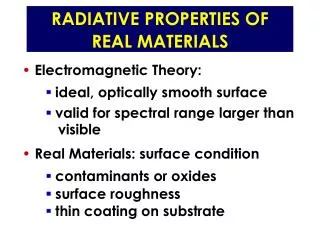
Relevance? • “Heat-transfer coefficients”: • view factors (can surfaces see each other? Radiation is “line of sight” ) • Emissivities (can surface radiate easily? Shiny surfaces cannot)
Basic Concepts of Network Analysis Analogies with electrical circuit analysis • Blackbody emissive power = voltage • Thermal Resistance (Real +Geometric) = resistance • Heat-transfer rate = current
T1,A1 qi1 T2,A1 TN,AN J1 J1 JN J2 . . . qi2 . J2 riGi Ei Gi . Ji . . Ebi Ji qi3 . J3 . . Ti,Ai JN-1 qiN-1 JN qiN Resistance Network for ith surface interaction in an Enclosure qi
A pure Radiating surface is characterized by real surface that is well insulated on one side and for which convection effects may be neglected on radiating side.
Surface 1 Surface 2 The Two-Surface Enclosure
Key Points for Two-Surface Example • How to do view factor arithmetic • How to use the concepts of view factors, surface resistances and view factor resistances to solve radiation problems • How to develop radiation networks • Application: storage of very cold (cryogenic) fluids (e.g. N2), Protection of Nuclear Reactor. • Popular as Radiations Shields. • Radiation shields are constructed from low emissivity (high reflectivity) materials.
Step 1: Sketch the Situation Surface 1, e < 0.1 Surface 2 : e 0.5
Step 2: Sketch Radiation Network • Surface and view factor resistances important. • One surface resistance for each surface. • One view factor resistance if one surface can see another.
Step 3: View Factor Concept: “Ant on A Surface” • Surface 1 (hemisphere): • When looking towards surface 2 (disk), can see both surfaces 1 and 2 (concave surface) • 0 < F11 < 1, 0 < F12 < 1 • Surface 2 (disk) • When looking towards surface 1, hemisphere, cannot see itself (flat or convex) • F22 = 0
View Factor Arithmetic • F21 = 1 - F22 = 1 • F12 = A2 F21 / A1
Key Points for Three-Surface Example Include a third surface, an adiabatic wall. How to treat adiabatic (= well-insulated) walls? • Application: performance analysis of solar energy collectors. • Development of Ideal Reradiators. • The term reradiator is common to many industrial applications. • With Q3 = 0, it follows from fundamentals that: J3=G3 J3=G3=E3=Eb,3
Example • Heating panels are located uniformly on the roof of a furnace, which is being used to dry out a bed of grains, which is situated on the floor.
Bed of grains on the floor Situation Perfect Reradiators
In What Context Might This Calculation Be Carried Out? • Suppose that you knew that the panels may burn out due to overheating if the panel temperature rises above a critical value. • Such a burn out would mean replacing the panels (expensive) and might also be a safety hazard (possibility of fire). • You would want to limit the energy input, because the panel temperature will rise as the energy input increases if the floor temperature stays the same. • This analysis would then tell you the critical heat flux. • The insulation on the adiabatic walls will also degrade, possibly with hazardous consequences, if the wall temperature gets too high (say at Tcrit). • We can also estimate the wall temperature.
Bed of grains on the floor Interpretation • All of the adiabatic walls see the same view of the other walls, so they can all be treated as one surface
Treatment of Adiabatic Walls • There is no heat flow through these walls (i.e. no equivalent of current), so • The emissivity of these walls does not matter. • The “blackbody” emissivity and the radiosity are the same, so • The temperature can be estimated from the radiosity. • These walls are just blank nodes in a radiation network. • Also called as Perfect Reradiators.
General Procedure • Draw up radiation network (always first) • In any order • calculate view factors, then view factor and surface resistances, then total resistances • calculate blackbody emissive powers (=voltages) • Calculate heat flows
Radiation Network 1 3 2
Explanation of Radiation Network • If a surface can see another surface, then there must be a view factor resistance between the two surfaces. • If the surface is not a blackbody, then it must have a surface resistance. • For an adiabatic surface, the surface resistance does not matter.
What Temperature are the Adiabatic Walls at the Moment? • Eb1, Eb2, J1, J2 and J3 all have units of W m-2 • There is no practical difference between the radiosity (J3) and the blackbody emissive power of the adiabatic walls. • If we know J3, then we can calculate T3 from:-
A Microwave • Microwave is generated using a Magnetron in a Microwave oven. • The radiation enters the cooking chamber through a waveguide. • The microwave is reflected by a rotating fan blade to evenly distribute the radiation throughout the cooking chamber. • Once entering the chamber, the radiation is reflected by the chamber walls until it is absorbed by the food. One of the major drawbacks of microwave is the hot spots. Microwave radiation, as it reflects around the cooking chamber, interact with other reflected radiation in such way that hot and cold spots are formed inside the microwave.
The phenomenon responsible for this is the interference of waves, shown in figure below. Waves overlapping in such way that the crests match one another interfere constructively, forming a hot spot. Waves which interfere destructively result in a cold spot. The uneven heating caused by these effects can be reduced significantly by using a rotary platform, included in many of the newer models of microwave ovens.