Download
1 / 12
120 likes | 262 Vues
Powering for the 2S-Module Random Thoughts. Katja Klein 1. Physikalisches Institut B RWTH Aachen University. CEC Meeting Aachen, 21st of March 2012. 3D-Model with realistic Buck Converter. DC-DC buck converter Components based on smallest v ersion of our pixel converters

E N D
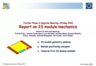
Powering for the 2S-Module Random Thoughts Katja Klein 1. Physikalisches Institut B RWTH Aachen University CEC Meeting Aachen, 21st of March 2012
3D-Model with realistic Buck Converter DC-DC buck converter Components based on smallest version of our pixel converters It fits on the “service hybrid“ Powering the 2S-Module
Buck Converter AC_PIX_V8_E We (Aachen group) develop buck converters based on CERN ASIC for pixel upgrade ASIC Our smallest board: V8 E: 2.6cm x 1.5cm; 1.5 -1.6g ASIC: AMIS4 by CERN Vout = 3.3V or 2.5V fs = 1.5MHz 2-layer PCB Toroidal plastic core inductor L = 450nH Pi-filters at in- and output • Why is a shield required? • to shield the magnetic emissions • as cooling contact for the coil • to segregate “noisy“ parts from output filters Powering the 2S-Module
Buck Converter Remote Control • Two features implemented in AMIS4: • Disable / enable input • Status bit (“power good“) • Need to be controlled from an independently powered unit, otherwise useless. • In phase-1 pixel detector, we plan to use the CCU as controller. • The Slow Control ASIC (SCA) of the GBT could be used for the outer tracker. • Since a “module controller“ is not foreseen, a “rod controller“ would be required. Vin Vin_Return Coil Vout ASIC Vout_Return Disable/enable Status DC-DC buck converter Powering the 2S-Module
Material Budget • Contribution of buck converter, comp. to CMS modules (1 converter per module) “Minimized“: Aluminium coil, no connector, less filter caps • Contribution of buck converter, compared to ATLAS stave (1 converter per hybrid) Powering circuitry itself might contribute with 5-10% to module material budget 1 normalized to respective module or stave area Novel Powering Schemes
The Conversion Ratio Conversion ratio: • Semi-conductor technology limits input voltage to Vin < 10V • We will need Vout = 1.2V • Maximal achievable conversion ratio is r = 10V / 1.2V = 6.7 • Cables channels can support 15kA • Total power of detector might be 57kW (Stefano Mersi) 48kA at 1.2V • Need r = 4.3 for 75% overall power efficiency • Want r as high as possible to decrease the cable material budget • All our studies (efficiency, noise, …) are currently performed for Vout = 2.5V and 3.3V • Previous measurements with AMIS2 showed efficiency of only 50-60% for Vout = 1.2V • AMIS4 does not provide a (straight-forward) possibility to switch Vout to 1.2V Powering the 2S-Module
Efficiency vs. Conversion Ratio AMIS2 with Vout = 1.2V AMIS2 with Vout = 3.3V AMIS4 with Vout = 3.3V Vin = 6V r = 1.8 Vin = 8V r = 2.4 Vin = 10V r = 3.0 Powering the 2S-Module
Power Requirements • CBC chips: 2 x 8 x 60mA = 1016mA @ 1.2V • Data concentrator: 2 x 170mA = 340mA @ 1.2V • ---------------------------------------------------------------------- • 1.36 A @ 1.2V • Low power GBT: official number is 500mW • But – at what voltages? Try to understand from Sandro Marchioro • GBT would require 420mA @ 1.2V and 400mA @ 2.5V Standard GBT best guess: GBTX: 1.4W at 1.5VGBSCA: of the order of 0.3W at 1.5VGBTIA: 0.25W at 2.5 – 3.0VGBLD: 0.75W at 2.5 – 3.0V } 500mW at 1.2V (if 65nm) } this will not change !? Total current requirement of 1.8A at 1.2V fits to buck converter current capability of 3A Note: bias current has to be provided conventionally Powering the 2S-Module
How to provide 2.5V (and 1.2V) • Need to provide of the order of 400mA at 2.5V • Several options: • Provide 1.2V from buck converter and provide 2.5V conventionally • Provide 1.2V from buck converter and use “1:2 step-up“ switched capacitor converter to derive 2.5V from 1.2V • Only the device from ATLAS is capable of providing 400mA • 1.2V x 2 2.5V • Provide 2.5V from buck converter and use “2:1 step-down“ switched capacitor converter to derive 1.2V from 2.5V • Switched cap. converter would be part of readout chip (+ data concentrator) • Such a device has been developed by CERN • First tests with CBC are promising • Would allow to operate buck converter with relatively low conversion ratio higher efficiency (e.g. 0.8 x 0.9 = 0.72) Powering the 2S-Module
Switched Capacitor DC-DC Converter • Two chips have been developed: • CERN (step-up and step-down, Iout = 60mA); used by CMS in CMS Binary Chip • From LBNL(step-down, Iout = 500mA); used by ATLAS in FE-I4 • Both with f = 1MHz • Both „divide-by-two“ 1 external capacitor (1µF 0402 or 0603) • Both chips do work • Efficiency lower than in simulation but still ~ 90% • Ripple large Phase-1: charge Phase-2: discharge CERN converter Novel Powering Schemes
Switched Capacitor DC-DC Converter • Switched capacitor converter by CERN is part of 130nm CMS Binary Chip • Used to convert 2.5V into 1.25V • Could be combined with buck converter large r • Works well, with efficiency of ~90% • Spurious charge injected by transients increase of noise, but only for high input capacitance (will have 2.7pF) • Same chip will be included in next, bump-bonded version of CBC (better coupling between grounds?) 1.78pF 5.79pF Novel Powering Schemes
Open Questions • DC-DC converter related • How to achieve an efficiency of ~ 80% for a large conversion ratio? • Find best combination of buck converter and switched capacitor converter • Reduce material of buck converter • Module related • Where to place DC-DC converter? Stave versus module • How to bring power to the module? Define connectors, cables etc. • How to bring power from converter to hybrids? One U-shaped hybrid vs. separate service hybrid • Implementation of control communication • Cooling of the DC-DC converter • Noise performance – system tests with CBC and module prototypes • Biasing Powering the 2S-Module