Download
1 / 33
330 likes | 501 Vues
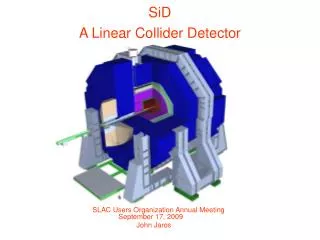
Linear Collider Project and Detector Concept Study. Akiya Miyamoto KEK September, 2004. Contents. International Linear Collider Physics Goals International activity: GDI A plan of the global experimantal program Detector concept study Detector requirements “Huge” detector. e. e.

E N D
Linear Collider Project and Detector Concept Study Akiya Miyamoto KEK September, 2004
Contents • International Linear Collider • Physics Goals • International activity: GDI • A plan of the global experimantal program • Detector concept study • Detector requirements • “Huge” detector
e e u u u u d d Role of e+e- Colliders • Historically, both pp and e+e- collider were crucial for the development of High Energy Physics • e+e- collision is an elementary process. • Less background • un-ambiguous measurements • well defined initial state ( energy and polarization ) e+e- coliders have been and will be crucial to establish a new principle ( Lagrangian for elementary particles )
The Linear Collider • LEP is the last circular e+e- collider • Future e+e- are linear collider. • Basic parameters of the next e+e- linear collider • Center of Mass Energy 250~1000GeV • Instantaneous Luminosity 2~3x1034/cm2/s • ~ 500/fb in several years • 50~100k Light Higgs boson production • Total accelerator length ~30km
Physics Goals of the Future LC • Search/Study Higgs boson(s) • Spin, Mass, Branching ratios • Search/study model independently • Resolve the hierarchy problem • SUSY: Searches for sparticles, determine mass, spin, couplings. • Neutralino is a good candidate of the dark matter • Extra-Dimensions: ee gg X and search virtual effects in SM processes. • Other possibilities: Little Higgs Model, • Precise determination of • Top quark mass and couplings • TGV and Quadric gauge boson couplings g key if Higgs is heavy • aS • Options • Giga-Z • gg collider
A History • In Japan, LC R&D was initiated in late 1980’s. • “JLC-I” report was published in 1992. It described physics, detector, and accelerator of JLC. • Accelerator R&D has been carried out based on warm cavity (X/C-band) technology. • In late 1990’s, ACFA Physics and detector working group was formed. • “ACFA Report” for physics and detector was published in 2002. • “GLC project report” was published in 2003.Reformation of Linear Collider Project under internation framework has proceed under ILCSC
Organization chart IUPAP ICFA (J.Dorfan) 3 regional steering com. ( Asia, N.A., Europe) ILCSC (M.Tigner) ALCSC Wold Wide Study ITRP (2004) (B.Barish) Acc. Sub-com (G.Glow) Phys.&Det. Sub-Com (J.Brau, H.Yamamoto, D.Miller) ACFA Phys.&Det. WG GDO Taskforace (2003/2004) (S.Ozaki) Parm.. Sub-com (R.Heuer)
International Technology Recommendation Panel (ITRP) • Warm technology (High gradiant 11GHz acc. ) has been studied by KEK/SLAC and their colleagues • Cold technology (Super Conducting Cavity ) has been studied by Tesla collab. • To realize the LC, international community should unit on a single technology for efficient use of resouces (Budget, man power, time ) • Thus ILCSC organized ITRP in late 2003. • ITRP met 6 times since Jan. 2004, visited 3 labs., and released recommendation in Aug. 2004. ITRP recommends the cold technology The project is now called ILC
GDI (Global Design Initiative) • GDI : An international rganization to develop the design of ILC. To be formed by 2005 basedon multi-lab MOU’s. • GDI schedule • 2005 : Complete accelerator CDR • 2006 : Initiate detailed engineering design • 2007 : Complete accelerator TDR • 2008 : Site selection and approval of international role and responsibilities by governments. • To proceed, three regional center(Asia, Europe, N.A) and the host of the central team will be setup.
KEK’s plan (Personal View) • Reorganization of LC accelerator R&D is under way • No decision yet • Has to be defined in GDI framework • Possible contribution of KEK ( will subject ot change ) • Development of Super RF cavity • Super RF cavity had been used at TRISTAN in early 90’s • KEK has been provided Super RF cavity for Tesla • Injector • Technologies developed at ATF will be applicable for the ILC injector • There would be more ….. • ILC is the very important future project of HEP. KEK would like to keep contributing the accelerator R&D. It will be the Asian regional center and may be the host of the central team. • The first ILC workshop will be held at KEK from Nov. 13 to 15.
Organizing the Global Experimental Program • GDI does not include detector studies. • Feb. 2004, the ILCSC has asked the Worldwide Study to develop a plan for organizing the experimental program in parallel with the GDI for the machine. • The WWS organizing committee and the community discussed at LCWS2004, Victoria workshop, etc anddeveloped the proposal, which was presented to the ILCSC in Aug. 2004.
ILCSC request to WWS • This plan should include the following: 1. Ensure that at least two different detector concepts are developed; by worldwide teams which will: - prepare CDR(s) on concepts, by ~2006; - be ready to form the cores of the collaborations when funding is in place and bids are called for. 2. Encourage and coordinate inter-regional R&D on essential detector technologies, and give peer-reviewed recognition to nationally funded R&D programmes as part of the worldwide project. 3. Make sure that vital questions of machine-detector interface and beamline instrumentation are as fully supported as accelerator and detector R&D. This will involve close links with the GDI
WWS Proposed timeline Experimental Program • Single preliminary costing document for at least one whole-detector produced by WWS Costing Panel • CDR’s from each detector concept team (expect some individuals to sign multiple) received by the WWS OC • Collaborations form and submit LOIs for proposal to the Global Lab (or GDO?) • Global lab selects experiments and asks for TDRs (2) GDI Timeline • 2004 – ITRP Technology Recommendation • 2005 – Accelerator CDR • 2007 – Accelerator TDR • 2008 – LC Site Selection • Site selection + 1 year
Proposed Panels • Costing panel: Request inputs from the teams studying each detector concept, ensure the same costing basis, and edit into a single document to be included with the accelerator CDR. Then the panel will stand down. • Detector R&D review panel: Maintain a register of relevant R&D, identify vital or missing activities, arrange for peer review of proposals, and endorse approved programs to funding agencies when requested. This panel will stand down when the detector proposals are finalized. • MDI panel: Liaise with GDI to coordinate MDI issues between accelerator and experimental teams, and ensure that essential MDI R&D is done. The panel will stand down when the global lab takes over this role. • More panels to be appointed as needed.
WWS Proposal WWS Organizing Committee proposes to: • Recognize and coordinate studies on whole detector concepts, and work toward interregional detector TDRs, including a cost document available at the time of the Accelerator CDR. • Interface with GDI, especially on MDI issues. • Keep a register of R&D relevant to LC experimental programs, identify those that are vital or missing, and ensure peer review of R&D proposals. • Organize interregional meetings and workshops. • Report to ILCSC and ICFA on the matters above.
Detector Concept Study • We started to discuss a new studies on LC detector concepts in Spring 2004 to follow the WWS proposal. • Breif presentations of the plan were presented • In July at Victoria (North American LC Workshop) • In September at Durham ( Europe LC Workshop ) • Kick-Off meeting is scheduled at 7th ACFA workshop in Nov. 9-12 at Taipei, Taiwan. See http://hep1.phys.ntu.edu.tw/ACFA7/ • A sereise of TV meetings have just started. Please join.
Detector Requirements • Detector requirements • Efficient & High purity b/c tagging • Good momentum resolution:For Higgs detection regardless of its decay mode. • Calorimeter:For W and Z separation in hadronic decay mode. • Hermeticity:For indirect measurements of invisible particles • Good background masking and time stamping capability GLC 3T model
GLC 3T Model configuration Detector parameters • Size: 8x8x6(Z) m3 • Solenoid: 3T • Calorimeter: • Lead./Scint. (Compensated) • EM(27X0): • Had(6.5l): • Tracker • Main: • Small cell jet chamber(CDC) • Inter Mediate Tracker • 5 layers of Si. • Vertex Detector • 4 layers of CCD
Impact of ITRP recommendation • ITRP recommended “Cold Machine” • Major Differences • Warm Machine : • 150Hz pulse, each ~200 bunches with ~1.4nsec separation • Event bunch ID is challenging. Enough time to read out between pulse • Cold Machine: • 5Hz pulse, each ~3000 bunches with ~300nsec separation • Needs to readout during the pulse (There are many other issues such as Energy spread, crossing angle, etc. ) • Implication to detector technology choice • Vertex Detector : Usual CCD is too slow to readout • Jet Chamber : Field distortion is not negligible • Calorimeter : Will have enough time for signal integration There are some room to improve detector design to best fit the Cold Machine
Figure of merit : Main Tracker The momentum resolution at lower energies is determined by multiple scattering
B=0 Figure of merit : Calorimeter • sjet2 = sch2 + sg2 + snh2 + sconfusion2+ sthreashold2 • Separation of charged particle and g/neutral hadron is important • Separation : BL2/Rm ( if consider curvature by B) • L=Rin(Barrel) or Zin(End Cap), • Rm=Effective Moliere length
Merit of Huge Detector • Good Jet Energy (Particle) Flow Measurement Good charged track separation in a jet at the inner surface of the calorimeter large BR2 • Pattern recognition is easier large n with thin material, small number of low momentum curling tracks • Good momentum resolution for charged particles large BR2 √n • Good dE/dx measurement for charged particles large n • Smaller relative volume of the dead space small ΔV/Vfor constant ΔV • Good two track separation, Larger efficiency for Ks and Λ (any long lived) large BR2 , larger R
“Huge Detector” model • Philosophy : Optimize for jet measurements • Energy : Particle Flow Analysis – Calorimeter + Tracker • Particles should be widely separated at the Cal. Surface. • Hermetic detector: Relative fraction of dead space can be made smaller • ID : Good vertex detector • Basic Design • Large inner radius of ECAL (R~2m) • Large lever arm for tracker • Good separation of particles at Cal. Surface • Moderate strength of magnet field: 2.5~3TCoil design : Radius is same as the GLC-3T model, but longer in Z. • To put long main tracker for good cosq coverage • To have enough distance from IP to the Cal. Suface. We call “Huge” but it is still smaller than CMS at LHC
Preliminary Mag. Field Calculation 7m 5.3m 4.85m 8.3m 4.5m 4.25m R4m 3.55m 2.35m 2.05m Iron R0.6m 0.4m Goal of magnetic field uniformity
Detector configuration under consideration “Huge” “GLC” design m m SC-coil SC-coil HCAL (Pb(Fe)/scinti or digital) Pb/scinti HCAL W/Scinti ECAL Pb/Scinti ECAL TPC (Jet chamber as option) Jet chamber Si intermedi.-Trk Si intermedi.-Trk SiVTX pixel(cold version) SiVTX pixel
Comparison of size of EM CAL surface • Area of EM CAL (Barrel + Endcap) • SD: ~40 m2 / layer • TESLA: ~80 m2 / layer • Huge: ~100 m2 / layer • (JLC-I: ~130 m2 /layer) Huge ~2.1m
A quick comparison : Tracker (numbers for `Huge’ are all tentative)
Vertex detector issues • Compared to 4T case, pair background hit at R= 15mm becomes x1.7 larger in 3T • At larger R, the background hit would decrease significantly • The configuration of R=20 mm with Si thickness < 70 mm and 500 mm thick beam pipe at R=12 mm still satisfies the requirement of sb=5 10/(pbsin3/2q) mm # of fired pixels ~ 5.0 pixels/hit TRC500 beam parameters Inner radius should be optimized based on physics performance using ILC parameter
Questions and challenges • How to reduce the ECAL cost? Which type of ECAL photo-sensor to chose? (Number of channels would be similar to other detector designs, though) • HCAL should be inside Magnet? Or can be put outside? How to support the heavy structure? • Silicon Vertex Inner radius : Background vs IP resolution • need ILC parameters. • Any essential impact on physics ? • Uniformity of the magnet is fine? Is structure strong enough ? • Crossing-angle? Which forward detector? --> need ILC parameters • How to mechanically support central tracking system including Final-Q ? …. …. …. ⇒Many challenges and open questions: Need detailed studies. New Participation are highly welcomed !
Summary • We will accelerate efforts towards the ILC and experiment there. • We are aiming to design a LC detector best optimized for “Particle Flow Algorithm”. We are now thinking to develop the “Huge” detector design. • Detailed studies have just started. There are a lot of open questions and challenges. • It will be a global efforts are we are looking for many partners in the world. • Mailing list will be open soon. Please watch http://ilcphys.kek.jp/ • A kick-off meeting will be held in Taipei in Nov. 2004.