Download

1 / 43
430 likes | 569 Vues
Integrated analysis of quench propagation in a system of magnetically coupled sole noids. Claudio Marinucci, Luca Bottura, Marco Calvi. CRPP, CERN, PSI. CHATS-AS 2011. Outline Introduction Model From 1D to 3D (THEA) POWER, SUPERMAGNET Results Reference case Parametric studies

E N D
Integrated analysis of quench propagation in a system of magnetically coupled solenoids Claudio Marinucci, Luca Bottura, Marco Calvi CRPP, CERN, PSI clam CHATS-AS 2011
Outline Introduction Model From 1D to 3D (THEA) POWER, SUPERMAGNET Results Reference case Parametric studies Summary clam
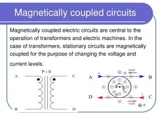
Problem Quench in coupled solenoids Given a system of magnetically coupled SC solenoids protected without external dump resistor, i.e. stored energy dumped in He Further to heat perturbation and quench in one coil Compute the evolution of currents, voltages and temperatures in all coils taking into account turn-to-turn and layer-to-layer thermal contacts #1 #2 #3 clam
Normal zone propagation in solenoids Longitudinal and transversal propagation Growth of normal zone bounded 1D, 2D and 3D Thin vs. thick solenoid Analytical solutions Propagation speed ? Large energy stored ? Coupled systems ? Wilson, 1983 clam
GPS Goal To demonstrate the capability of the model and test its potential to extrapolation to configuration “other” than CICC’s Procedure Longitudinal and transversal quench propagation Thermal and electrical analysis in parallel Solution CryoSoft™ codes THEA POWER SUPERMAGNET Integrated analysis clam
Outline Introduction Model From 1D to 3D (THEA) POWER, SUPERMAGNET Results Reference case Parametric studies Summary clam
From 1-D to 3-D Layer 1, Turn 1-4 Layer 2, Turn 1-4 Example: 2 Layers, 4 Turns Layer 1, Turn 1 start (X=0) Layer 2, Turn 4 end (X=L) Layer 2, Turn 1 start Layer 1, Turn 4 end Thermal connections between layers and turns are required X=0 X=L clam
THEA model Finite element code for the Thermal, Hydraulic and Electric Analysis of superconducting cables (CICC, also but not only) T0 Ti X X+DX THEA is a 1-D code with 3-D capability X (along conductor length) Diffusion Longitudinal Joule’s heat Internal (SC physics) Heat exchange among solids and with coolants Transversal clam
THEA transversal thermal model User routine Example: 7 Turns, 6 Layers thins Helium bath (T0) P4 P0 L1 L2 L3 L4 L5 L6 T1 P2 thins P0 = perturbation P2 T2 T T4 Zc T1 T3 T4 T3 T T4 Xc T2 T5 T2 P2 = kins/thins XC (T2-T) P4 = kins/thinsZC (T4-T) T6 1D + 2D = 3D T7 clam clam 9
SUPERMAGNET model SUPERMAGNET joins and manages existing [and validated] tools in a customizable, flexible, and powerful environment for the analysis of superconducting magnet systems This analysis: 3x THEA (1 per coil) POWER SUPERMAGNET Calvi, Bottura, Marinucci, CHATS-AS 2008 (Tsukuba) clam
POWER model I1 I3 POWER is a program for the simulation of electric networks (resistances, inductances, current and voltage sources) THEA-1 I2 THEA-2 Protective resistors RD1 & RD2 to limit voltages in system THEA-3 clam
Outline Introduction Model From 1D to 3D (THEA) POWER, SUPERMAGNET Results Reference case Parametric studies Summary clam
Reference case Simple model magnet Squared conductor (all coils) Magnetic field: B = 7 T, constant in time and space (all coils) Inductances: L1 = 0.61 H, L2 = 1.47 H, M12 = 0.69 H (I0 = 147 A, E = 37 kJ) Protective resistors: RD1 = 0.5 Ohm, RD2 = 1 Ohm Insulation: thINS = 50 mm, kINS = 0.100 W/mK (th. conductivity of glass-epoxy @20K) Helium bath: T0 = 4.2K, h = 100 W/m2K Perturbation: P0 = 10 W/m in Coil #1 along 1 m (4 turns) for 10 ms FEM: 5000/4000 elements (Coil #1/Coil #2,#3) #2 Coil #1 #3 Øin Parametric studies clam
Results of reference case Current and resistance Quench in Coil #1 generated by 10 W heat input Coil #1 Coil #1 Quench is instantaneous Quench in Coil #2 induced by current overloading (I>Ic) Coil #2 Coil #2 Quench starts at t = 0.14 s clam
Results of reference case Temperature distribution in X @ 0.01s < t < 5s (Coil #1) Nlayer Nturn Local normal zones in first 100 ms in all layers Coil #1 1 layer = 255 turns (278 elements) Full normal length after 200 ms Nlayer 1 2 4 6 8 10 12 14 16 18 X [m] clam
Results of reference case Temperature in Coil #1 Heat exchange to helium clam
Results of reference case Current and voltage Current overload in Coil #2 due to inductive coupling clam
Results of reference case Quench induced in Coil #2 Coil #2 0.01s < t < 0.10s, NO QUENCH Quench in Coil #2 is current driven -> full length is normal from start of quench Coil #2 0.10s < t < 1s, QUENCH clam
Outline Introduction Model From 1D to 3D (THEA) POWER, SUPERMAGNET Results Reference case Parametric studies Summary clam
Parametric studies # 1. Thermal conductivity of insulation kINS = 0.0 – 0.200 W/mK reference case: 0.100 W/mK, glass epoxy at 20K # 2. Heat transfer coefficient to He bath h = 0 – 500 W/m2K reference case: 100 W/m2K # 3. Protective resistor RD1 and RD2 multiplying factor = 1 – 5 reference case: 1 (RD1 = 0.5 Ohm, RD2 = 1.0 Ohm) clam
Parametric study #1 Current vs. Time For lower kINS (worse thermal coupling between layers and turns) * Longer current decay time constant * Quench in Coil #2 starts at a later time (no quench for kINS = 0.010 and 0.0 W/mK) Coil #1 kINS = 0.010 W/mK Recovery in Coil #2 Coil #2 clam
Parametric study #1 T vs X @ 0.01s < t < 0.10s (Coil #1) Coil #1 kINS = 0.200 W/mK kINS = 0.002 W/mK clam
Parametric study #1 T vs X @ 0.10s < t < 5s (Coil #1) Coil #1 * Less uniform temperature distribution in X for lower kINS * Hot spot temperature not strongly dependent on kINS (except for kINS = 0) kINS = 0.100 W/mK Tmax = 190 K kINS = 0.0 W/mK h = 100 W/m2K kINS = 0.010 W/mK kINS = 0.002 W/mK clam
Parametric studies # 1. Thermal conductivity of insulation kINS = 0.00 – 0.20 W/mK reference case: 0.10 W/mK, glass epoxy at 20K # 2. Heat transfer coefficient to He bath h = 0 – 500 W/m2K reference case: 100 W/m2K # 3. Protective resistor RD1 and RD2 multiplying factor = 1 – 5 reference case: 1 (RD1 = 0.5 Ohm, RD2 = 1.0 Ohm) clam
Parametric study #2 T vs X @ 0.1s < t < 5s Coil #1 h = 500 W/m2K • * Less uniform temperature distribution in X for larger h (same qualitative results in Coil #2) • * Hot Spot temperature is independent of h (also in case of adiabatic BC’s) h = 100 W/m2K Adiabatic BC’s clam
Limiting case kINS = 0 W/mK and h = 0 W/m2K Coil #1 Tmax = 250 K Tmax = 68 K (Ref. case) kINS = 0 W/mK h = 0 W/m2K No quench in Coil #2 clam
Parametric studies # 1. Thermal conductivity of insulation kINS = 0.00 – 0.20 W/mK reference case: 0.10 W/mK, glass epoxy at 20K # 2. Heat transfer coefficient to He bath h = 0 – 500 W/m2K reference case: 100 W/m2K # 3. Protective resistor RD1 and RD2 multiplying factor = 1 – 5 reference case: 1 (RD1 = 0.5 Ohm, RD2 = 1.0 Ohm) clam
Summary for Tmax (Coil #1) Hot spot temperature not strongly dependent on 3 parameters investigated (except kINS = 0) Magnet protection: Safe conversion of magnetic energy into thermal energy without risk of damaging components, i.e. minimize Tmax , DTmax and Vmax Reference case clam
Summary for MIITs (Coil #1) Reference case clam
Summary for Vmax (Coil #1, #2) Quench voltage Reference case clam
Summary Quench in coupled solenoids is a typical SC magnet design problem, and it can be analyzed using a tailored assembly (SuperMagnet) of selected CryoSoft™ codes (THEA, POWER). The topology is obviously not a limiting factor. User routines were included in the THEA code to take into account the transversal heat transfer and propagation. The quenching coil resistance was used in a circuital model with lumped parameters (POWER). Other features (e.g. variable magnetic field) can be included easily. Modeling provides access to hidden parameters (e.g. internal voltage) and parametric analysis in a homogeneous and self-consistent framework clam
Thank you for your attention clam CHATS-AS 2011
SUPERMAGNET model THEA POWER t0 SUPERMAGNET clam
SUPERMAGNET model THEA POWER t0 SUPERMAGNET clam
SUPERMAGNET model THEA POWER SUPERMAGNET t0 clam
SUPERMAGNET model THEA POWER SUPERMAGNET t0 clam
SUPERMAGNET model THEA POWER SUPERMAGNET t0 clam
SUPERMAGNET model THEA POWER SUPERMAGNET t0 clam
SUPERMAGNET model THEA POWER SUPERMAGNET t0 clam
SUPERMAGNET model THEA POWER SUPERMAGNET t0 clam
SUPERMAGNET model THEA POWER SUPERMAGNET t0 clam
SUPERMAGNET model THEA POWER SUPERMAGNET t0 clam
SUPERMAGNET model THEA …and so on POWER SUPERMAGNET t0 clam