Download
1 / 21
250 likes | 501 Vues
Dr. Catherine Turner. Assembly drawings. When a product has more than one part, an assembly drawing is necessary to show how the product is assembled when it is finished. It shows someone a general idea about how the finished product is supposed to look.

E N D
Dr. Catherine Turner Assembly drawings
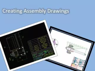
When a product has more than one part, an assembly drawing is necessary to show how the product is assembled when it is finished. It shows someone a general idea about how the finished product is supposed to look. • It is called a working drawing that tells what is made, what material to use, what tolerance is applicable, and other critical information. • The assembly drawing can have as many views as needed to show all the parts. • A sectional view is often included to show the material used for one or more parts and also to show how the final product is assembled. • If any of the parts have an inclined plane, an auxiliary drawing is included somewhere in the plans. • Each part has a circled number that is used in an accompanying table to show critical information needed to manufacture the parts and to assemble the product. Assembly Drawing -
Engineering Design suggests that we use as many kinds of views as necessary to fully document and to show each part of a product, including sectional views to show materials, and auxiliary views for inclined parts. An assembly drawing is often necessary to provide all the information needed to take an idea from the sketch pad to full production. The following slides contain all the information you need to answer the questions on the Worksheet and to get started with your own assembly drawings. What views do we use?
Usually a sketched idea, the design layout is a rough draft of the finished drawing. It is recommended that the engineering designer use standard parts as much as possible as well as including established methods of manufacturing. If a manufacturer has to completely change their machinery to make a part just for you, the price may take your product out of the market. Usually parts are not dimensioned in the design layout. That is added in on the formal drawings. Design Layout -
The detail drawing shows each individual part with a drawing number and title, including all required information for manufacture. NOTE: Each individual part has it’s OWN page. The detail drawing will include dimensions, location on the assembly drawing, all required views, and a title block that includes part specifications. As mentioned in the assembly drawing, an auxiliary view is required to show the true length and width of any part that has an inclined plane. The auxiliary view is often shown on the detail drawing when applicable. Detail Drawing -
Nuts, bolts, washers and other ‘on the shelf’ items are considered standard and do not require their own detail drawing. Purchased parts are simply identified on the assembly drawing by size, material type, and finish. It is recommended that engineering designers use purchased and standard items as much as possible for ease of manufacturing and cost effectiveness. Purchased Parts -
Sometimes parts are permanently fastened and cannot be taken back apart once assembled. This need to be shown and identified in a separate, subassembly drawing. For example, two parts that are welded together require their own subassembly drawing. Subassembly drawing -
If every piece of information necessary to manufacture each part were placed on an assembly drawing, the drawing itself would be covered in information. To minimize confusion and to clarify pertinent information, a circled number is often identified with a leader line (arrow head with text) which correlates to a number in a chart either on the drawing or on attached documentation. Callout, Balloon, and Bill of Materials - 1
This information is then used to generate a BOM or Bill of Materials that has all the important information for the part that matches the circled number. BOM
Item Number • Matches the callout or balloon number on the drawing. • Description of the design • Short and sweet information about the specific part. • Manufacturers Part Number • This will be assigned by the manufacturer and does NOT match the item number on the assembly drawing and BOM Suggested Important Information for bom
Manufacturer • Most companies will specify a manufacturer for a part and is often dependent on the purchasing agent who negotiates the best prices and delivery • Material Used • Because the strength, quality, compression and tension resistance and other properties differ with the materials, it is critical that the engineering designer research and choose the best material for the product. More BOM possible information
Quantity • How many of each part do you need? • If you say 1, it is read as 1 part. • If you really mean 1 gross and just put 1 on your BOM, don’t be surprised when you are 143 short of whatever it is you need. • A gross is 12 dozens or 12 x 12 = 144. • Often, standard small parts like washers, bolts, and fasteners are sold by the gross. • Remember that people ordering your stuff will use your BOM and most will not be able to read your mind so be sure and put AS MUCH information as possible that someone would require to get your correct parts. And More BOM possible information
Callouts and balloons are used every time, on every part on an assembly drawing, to keep the drawing as clean as possible. Callouts & Balloons 1
This is how your bill of materials match the Callouts & Balloons…
Just a suggestion for important information: • Item Number • Description • Manufacturer Part Number • Manufacturer • Material • Quantity For our assignments, we will generate our own BOM, either in the title block, or on a word processing or database document.
Assembly drawings all have title blocks and that is where the similarity from one drawing to another ends. Companies all have their own ideas of what is needed in the title block so it is a good idea to view existing drawings when starting a new position that requires assembly drawings. When drawings are changed, a revision number is placed on the title block and the date so that someone looking at all the drawings later can determine the most current version. Title Block
Company name and address What the product is (drawing title) The part number The scale of the drawing Who is the drafter and when was the drawing finished or submitted Who checked the drawing and the date checked Who approved the drawing and the date approved What material was used for the part What are the tolerances Any heat treatments or finishing not specified on the drawing Common information in a title block
Just like the title blocks, the numbering systems vary from one company to the next. It is common for drawings to be sequential and the numbers followed by a letter that states the size of the paper. For example, drawing 33800 on a size B sheet of paper could be numbered B-33800 in most situations. Numbering Systems
Show what the finished product is supposed to look like Show where all the parts are located for assembly Have information on a separate table (parts list or Bill of Materials) that matches identifying circled numbers on the assembly drawing May have several views in order to show all the important details on the product Has all the information needed to produce a part Reminder – Assembly Drawings