Download
1 / 9
90 likes | 190 Vues
Exploring the efficiency of I/O device controllers by implementing shadow memory to track register writes and minimize read-back multiplexing. Learn how shadow memory streamlines device operation and reduces costs in system design.

E N D
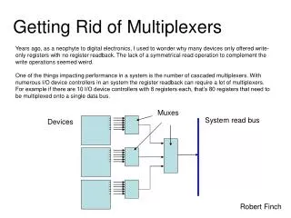
Years ago, as a neophyte to digital electronics, I used to wonder why many devices only offered write-only registers with no register readback. The lack of a symmetrical read operation to complement the write operations seemed weird. One of the things impacting performance in a system is the number of cascaded multiplexers. With numerous I/O device controllers in an system the register readback can require a lot of multiplexers. For example if there are 10 I/O device controllers with 8 registers each, that’s 80 registers that need to be multiplexed onto a single data bus. Getting Rid of Multiplexers Muxes System read bus Devices Robert Finch
Getting Rid of Multiplexers • Being able to read back an I/O device control register is of limited value, and multiplexers can be expensive. The typical solution then of many I/O device controllers is to not have registers that can be read back. If the register value is going to remain static (if it’s non-volatile) typically a write-only register is implemented. It’s left up to software to keep track of values written to registers if needed. • The device controllers use write-only registers to avoid the expense of read-back multiplexers, except in cases where read-back is absolutely necessary. One cannot implement a UART receiver for instance, without being able to read the receive register. • Is there a way to obtain register feedback and avoid read-back multiplexers in I/O devices ?
Getting Rid of Multiplexers • Another solution to write only registers or tons of multiplexers, is to use an I/O shadow memory that tracks writes to I/O device controller registers and maintains a copy. This is essentially the operation that’s normally done by software, implemented with hardware. Muxes System read bus Less readback multiplexing needed Devices I/O Shadow Memory
Getting Rid of Multiplexers • Typically, I/O device controller registers are grouped together into a region of the memory map (or I/O map) of the system. • The I/O shadow memory occupies and responds to the same range of addresses as the I/O controller registers. I/O Shadow Memory Overlays the same address range for several devices. I/O Device Memory Map $D00x Device $D0xx $D01x Device Device $D02x
Getting Rid of Multiplexers • In order to avoid conflicting reads, the read-back path from the I/O devices is ignored, and instead reads come from the shadow memory. Writes can occur simultaneously to both I/O device control registers, and the shadow memory. The shadow memory keeps track of data written to the I/O registers by maintaining it’s own copy. • In cases where it is necessary to read an I/O register because it is updated externally, read-back from the shadow memory has to be disabled, and a read from the I/O device has to occur. • In order to support an I/O shadow memory, the I/O controller needs to supply a signal indicating when a volatile register is being read. volatile registers System read bus Non-volatile register readbacks removed volatile register signal I/O Shadow Memory shadow memory gate • Memory cells modified by external agents are typically called volatile memory locations.
Getting Rid of Multiplexers • Example: • A video display controller contains registers allowing the number of rows and columns to be configured. Since these registers are not updated in an external hardware fashion, they are typically implemented as write-only registers. The number of rows and columns visible on the video display is something that is often maintained or used by software. As the display is updated, software needs to know how many rows or columns are present, so typically a copy of this information is maintained in a software config area. • These registers are candidates for the I/O shadow memory. A second example is a cursor position register. Adjusting the cursor position is often implemented as a read-write register. Using a shadow memory, this register can be made write-only in the video controller, while the value can still be read from the I/O shadow memory.
Getting Rid of Multiplexers The vol_o signal. • The shadow memory could be implemented as part of the I/O device controller, and not an independent memory. However this results in an inefficiency in the way memory is used. Memory in a electronic device typically comes in block form. There is often far more memory in the block memory resource than would be required by a single I/O device. It makes sense then to share the memory capacity of a single memory resource amongst several I/O devices. • In order to use a shadow memory system, the system needs to know when a volatile I/O register is being read. Hence a signal (I call it “vol_o”) needs to be supplied by the I/O device.
Getting Rid of Multiplexers • Example: • Read-back from a serial uart. The uart actually contains about a dozen registers • for configuration. However there are only four volatile registers. The other config • registers are non-volatile in nature. In the example below, only the four volatile • registers are multiplexed onto the data bus. A signal “vol_o” is generated indicating the read-back would be from a volatile register. This allows the other registers to be implemented in a I/O shadow memory. • // mux the reg outputs • always @* • if (cs) begin • case(adr_i[3:0]) // synopsys full_case parallel_case • `UART_MS: dat_o <= {dcdx[1],1'b0,dsrx[1],ctsx[1],dcd_chg,3'b0}; • `UART_IS: dat_o <= {irq_o, 2'b0, irqenc, 2'b0}; • `UART_LS: dat_o <= {1'b0, tx_empty, tx_empty, 1'b0, frame_err, 1'b0, over_run, data_present_o}; • default: dat_o <= rx_do; • endcase • end • else • dat_o <= 8'b0; assign vol_o = cs && adr_i[3:2]==2'b00;
Getting Rid of Multiplexers • As a last note, note that in the example the data output is set to zero, when the device is deselected. This allows the output to be combined with other devices in a ‘wired-or’ fashion. This also helps to eliminate multiplexer use. • The value of the I/O shadow memory is that it allows all the registers that contain non-volatile data to be implemented as write-only registers in I/O device controllers. Read-back for these registers can come from the shadow memory. • Sometimes, the I/O shadow memory can be found almost for “free”. If the I/O map overlays a small portion of a RAM all that’s needed is a little bit of control logic. For instance in a system with a 16MB memory map, a 16MB ram might be in use. ROM and I/O locations mapped into the memory map, “override” the RAM access at various points in the memory map.