Download
1 / 18
180 likes | 395 Vues
VCL-SafeComm 16 E1 Links (48 E1 Ports) (1+1 Automatic Protection Switch) Product Presentation. xcvcxv. Orion Telecom Networks Inc. - 2012. Updated: Aug, 2012. Product Overview.

E N D
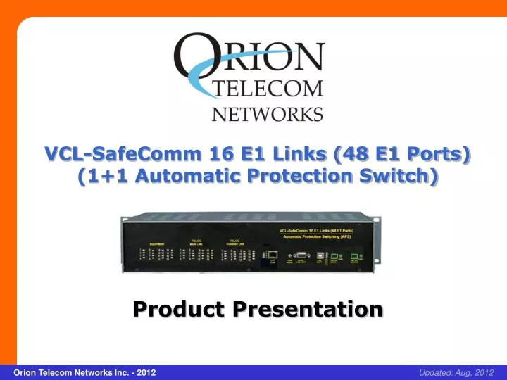
VCL-SafeComm 16 E1 Links (48 E1 Ports) (1+1 Automatic Protection Switch) Product Presentation xcvcxv Orion Telecom Networks Inc. - 2012 Updated: Aug, 2012
Product Overview • Used to protect upto 16 point-to-point E1 links and to provide an alternate communication route for each E1 Link between any two points in a network • In the event of the failure of the primary (main) E1communication route, the VCL-SafeComm, 16 E1 Links 1+1 APS equipment, automatically switches the E1 traffic to a secondary (standby) E1 route • May also be used in point-to-multi-point applications to provide 1+1 Protected / Alternate Routing Path between multiple locations. • Data transported on the E1 Links is transparent and protocol independent • SNMP V2 Traps for alarm reporting. • Available in a 2U high, 19-Inch rack mount chassis.
Applications: • Allows the user to design 1+1 (protected) redundant E1 routes on similar (fiber-fiber), or complementing (fiber-radio) transmission mediums • Transport A-bis Interface on redundant E1 links • Provide 1+1 Protection / Alternate Routing Path between BSC and BTS • Used to design 1+1 redundant (protected) E1 rings on PDH networks, which otherwise would not be possible with PDH technology • The criterion for switching between the primary (main) and the secondary (protected/standby) routes is user programmable is Loss-Of- Signal on E1 links, or AIS (All-Ones AIS alarm) condition • May be used in a point-to-multipoint configuration to provide 1+1 Protected / Alternate Routing Path between one location and multiple locations (as shown in application diagram).
Features and Highlights: • High density protection switching equipment (upto 16 E1 Links i.e. 32 E1 Ports) • Ensures that mission critical voice, data, control and management traffic links are maintained even if either the primary or the secondary E1 backhaul transmission links fail • When the primary (working) link fails, the E1 traffic is automatically switched to the standby (secondary) link to ensure maximum link uptime • Offers comprehensive remote configuration and alarm management capabilities of the VCL-SafeComm, 16 E1, 1+1 Automatic Protection Switching • Equipment the product may be used to improve network reliability and control • Increased network reliability through link resilience.
Features and Highlights: • Media and Path Diversity • Remote Management • Alarm logging and monitoring • Dual -48V DC Power Inputs. User Programmable 1+1 Protection Switching Parameters: • Loss of Signal • AIS (All Ones Alarm) • “External Trigger” option - to switch between “primary” and “standby” E1 Links (the external trigger shall be a contact “open” or “closed” condition)
Security and Password Features: System Access, Control and Management Options: • Telnet • SSH • CLI Control Interface (HyperTerminal or VT100) • SNMP V2 Traps (MIB File provided) • Windows based GUI (Graphical User Interface) for easy configuration, management and access. Ability to monitor multiple units from a single NMS. OAM: Operation and Management Ports: • RS232 Serial Port • USB COM Port • 10/100BaseT Ethernet for remote access.
Security and Password Features: SecurityandProtection: • Secured Access via SSH V2 • Password Protection: Password Protection in compliance with the mandatory clauses of the GR-815-CORE-2 specifications for secured access control. CLI Control Interface (HyperTerminal or VT100) • Logging: Maintains a log of all successful and un-successful attempts. • Logged information includes the ID and the IP address of the accessing entities. • Alerts the administrator if the un-successful logging attempts exceed three. • Security Audit: All access logs for up to 30 days are maintained for security audit purposes. • Security log entry of any request or activity including that user-ID (including IP address, if applicable), to establish user accountability • Report Generation / Audit Trail • Security Administration.
Management and Monitoring: • RS232 serial, USB serial interfaces for local terminal access. • 10/100BaseT Ethernet Interface for remote access over an IP network. • Encrypted Password Protection. • Telnet – Remote access over IP links. • SSH – Secured remote access using Secure Shell Protocol over IP links. • SNMP Traps and NMS for real time remote monitoring and management over an IP network. • Automatic Link Test feature link testing at user programmable periodical intervals. • Visual I/O status LED Display.
Modes of Operation: • There are three modes in which the VCL-SafeComm E1, 1+1 Automatic Protection Switch can be configured to operate in: • AUTOMATIC SWITCHING MODE • EXTERNAL TRIGGER SWITCHING MODE • MANUAL SWITCHING MODE
AUTOMATIC SWITCHING MODE • The VCL-SafeComm can be configured to operate in an AUTOMATIC SWITCHING MODE. In the automatic mode, the switch shall automatically switch and re-route the E1 circuits from the MAIN route to the STANDBY route if there is an AIS or a LOS (LOSS OF SIGNAL) alarm, on the MAIN E1 link route. • Similarly, in the automatic mode the switch shall automatically switch back and re-route the E1 circuits from the STANDBY route to the MAIN route, upon the restoration of the service on the MAIN E1 link route. • All switching parameters and link restoration parameters are user programmable.
EXTERNAL TRIGGER SWITCHING MODE • Sometimes the user wants to switch the E1 circuits between the MAIN route and the STANDBY route when some external event occurs. • In the EXTERNAL TRIGGER MODE, the user can switch between the MAIN E1 route and the STANDBY E1 route when an external trigger (such as an closed/opened physical contact) is applied to the switch. • This unique feature is used by certain radios equipment suppliers, where they apply an external trigger to switch and re-route the E1 circuits between their main E1 radios and standby E1 radios.
MANUAL SWITCHING MODE • In Manual Switching Mode, the user shall use manual Telnet commands to switch the E1 circuits between the MAIN route and the STANDBY route, manually, using Telnet commands. • In this mode the AUTOMATIC MODE and the EXTERNAL TRIGGER MODE are both disabled and the manual commands over ride all other modes.
Switching Criterion and Time E1 Switching Criterion User Programmable 1+1 Protection Criterion a) Loss of Signal b) AIS (All Ones Alarm) Minimum E1 Switching Time from 10 milliseconds to 3000ms (User Programmable) Main Link To Standby Link Minimum E1 (Recovery) Switching 10 milliseconds to 9999ms (User Programmable) Time From Standby Link to Main Link Switching Mode User can program the APS to stay on Standby Port a) Auto when the Main link is restored. b) Force ON Main c) Force ON Standby
Application Diagram - To provide redundant routes over diverse media: SafeComm 8 E1 Links (24 E1 Ports)
Thank you for your attention For more details visit us at our Website at http://www.oriontelecom.com Headquarters: Phoenix, Arizona Orion Telecom Networks Inc. 16810, Avenue of the Fountains, Suite # 108, Fountain Hills, AZ 85268 U.S.A. Phone: +1 480-816-8672, Fax: +1 480-816-0115 E-mail: sales@oriontelecom.com Website: http://www.oriontelecom.com Regional Office: Miami, Florida Orion Telecom Networks Inc. 4000 Ponce de Leon Blvd. Suite 470, Coral Gables, FL 33146 U.S.A. Phone: 1-305-777-0419, Fax: 1-305-777-0201 E-mail: sales@oriontelecom.com Website: http://www.oriontelecom.com