Download
1 / 67
770 likes | 1.94k Vues
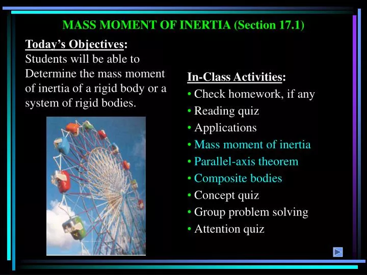
MASS MOMENT OF INERTIA (Section 17.1). Today’s Objectives : Students will be able to Determine the mass moment of inertia of a rigid body or a system of rigid bodies. In-Class Activities : • Check homework, if any • Reading quiz • Applications • Mass moment of inertia

E N D
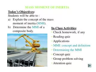
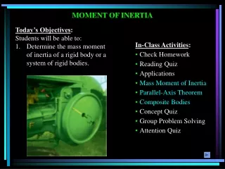
MASS MOMENT OF INERTIA (Section 17.1) Today’s Objectives: Students will be able to Determine the mass moment of inertia of a rigid body or a system of rigid bodies. In-Class Activities: • Check homework, if any • Reading quiz • Applications • Mass moment of inertia • Parallel-axis theorem • Composite bodies • Concept quiz • Group problem solving • Attention quiz
READING QUIZ 1. Mass moment of inertia is a measure of the resistance of a body to A) translational motion. B) deformation. C) angular acceleration. D) impulsive motion. 2. Mass moment of inertia is always A) a negative quantity. B) a positive quantity. C) an integer value. D) zero about an axis perpendicular to the plane of motion.
APPLICATIONS The flywheel on this tractor engine has a large mass moment of inertia about its axis of rotation. Once the flywheel is set into motion, it will be difficult to stop. This tendency will prevent the engine from stalling and will help it maintain a constant power output. Does the mass moment of inertia of this flywheel depend on the radius of the wheel? Its thickness?
APPLICATIONS (continued) The crank on the oil-pump rig undergoes rotation about a fixed axis that is not at its mass center. The crank develops a kinetic energy directly related to its mass moment of inertia. As the crank rotates, its kinetic energy is converted to potential energy and vice versa. Is the mass moment of inertia of the crank about its axis of rotation smaller or larger than its moment of inertia about its center of mass?
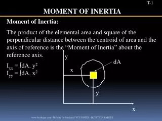
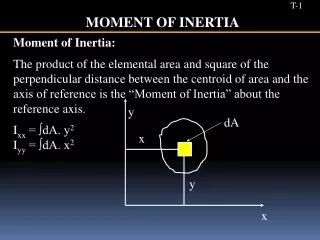
The mass moment of inertia is a measure of an object’s resistance to rotation. Thus, the object’s mass and how it is distributed both affect the mass moment of inertia. Mathematically, it is the integral I = r2 dm = r2r dV In this integral, r acts as the moment arm of the mass element and r is the density of the body. Thus, the value of I differs for each axis about which it is computed. m V MOMENT OF INERTIA In Section 17.1, the focus is on obtaining the mass moment of inertia via integration.
MOMENT OF INERTIA (continued) The figures below show the mass moment of inertia formulations for two flat plate shapes commonly used when working with three dimensional bodies. The shapes are often used as the differential element being integrated over the entire body.
PROCEDURE FOR ANALYSIS When using direct integration, only symmetric bodies having surfaces generated by revolving a curve about an axis will be considered. Shell element • If a shell element having a height z, radius r = y, and thickness dy is chosen for integration, then the volume element is dV = (2py)(z)dy. • This element may be used to find the moment of inertia Iz since the entire element, due to its thinness, lies at the same perpendicular distance y from the z-axis. Disk element • If a disk element having a radius y and a thickness dz is chosen for integration, then the volume dV = (py2)dz. • Using the moment of inertia of the disk element, we can integrate to determine the moment of inertia of the entire body.
1 1 rpx4 rp p(1000) 8 ò ò = = = = 174.5 kg•m2 Iy dy y dy 2 2 18 0 0 EXAMPLE 1 Given: The volume shown with r = 1000 kg/m3. Find: The mass moment of inertia of this body about the y-axis. Plan: Find the mass moment of inertia of a disk element about the y-axis, dIy, and integrate. Solution: The moment of inertia of a disk about an axis perpendicular to its plane is I = 0.5 m r2. Thus, for the disk element, we have dIy = 0.5 (dm) x2 where the differential mass dm = r dV = rpx2 dy.
I = IG + md2 where IG = mass moment of inertia about the body’s mass center m = mass of the body d = perpendicular distance between the parallel axes PARALLEL-AXIS THEOREM If the mass moment of inertia of a body about an axis passing through the body’s mass center is known, then the moment of inertia about any other parallelaxis may be determined by using the parallel axis theorem,
Radius of Gyration The mass moment of inertia of a body about a specific axis can be defined using the radius of gyration (k). The radius of gyration has units of length and is a measure of the distribution of the body’s mass about the axis at which the moment of inertia is defined. I = m k2 or k = (I/m) PARALLEL-AXIS THEOREM (continued) Composite Bodies If a body is constructed of a number of simple shapes, such as disks, spheres, or rods, the mass moment of inertia of the body about any axis can be determined by algebraically adding together all the mass moments of inertia, found about the same axis, of the different shapes.
å miyi 1( 10 ) + 2 ( 10 ) = = = y 1.5 m å + 10 10 mi EXAMPLE 2 Given: Two rods assembled as shown, with each rod having a mass of 10 kg. Find: The location of the center of mass G and moment of inertia about an axis passing through G of the rod assembly. Plan: Find the centroidal moment of inertia for each rod and then use the parallel axis theorem to determine IG. Solution: The center of mass is located relative to the pin at O at a distance y, where
The moment of inertia IG may then be calculated by using the parallel axis theorem. IG = [I + m(y-1)2]OA + [I + m(2-y)2]BC IG = [3.33 + (10)(0.5)2] + [3.33 + (10)(0.5)2] IG = 11.66 kg·m2 EXAMPLE 2 (continued) The mass moment of inertia of each rod about an axis passing through its center of mass is calculated by using the equation I = (1/12)ml2 = (1/12)(10)(2)2 = 3.33 kg·m2
2. The mass moment of inertia of a thin ring of mass m and radius R about the Z axis is ______ . A) (1/2) m R2 B) m R2 C) (1/4) m R2 D) 2 m R2 CONCEPT QUIZ 1. The mass moment of inertia of a rod of mass m and length L about a transverse axis located at its end is _____ . A) (1/12) m L2 B) (1/6) m L2 C) (1/3) m L2 D) m L2
GROUP PROBLEM SOLVING Given: The density (r) of the object is 5 Mg/m3. Find: The radius of gyration, ky. Plan: Use a disk element to calculate Iy, and then find ky. Solution: Using a disk element (centered on the x-axis) of radius y and thickness dx yields a differential mass dm of dm = r p y2 dx = r p (50x) dx The differential moment of inertia dIy’ about the y-axis passing through the center of mass of the element is dIy’ = (1/4)y2 dm = 625 r p x2 dx
Integrate to determine Iy: Iy = 21.67x10⁹rp 200 625 50 ò ò = = + = + Iy dIy rp(625x2 50x3)dx rp[( )(2003) ( )(2004)] 3 4 0 The mass of the solid is Therefore Iy = 21.67x10³ m and ky = Iy /m = 147.2 mm 200 ò ò = = = = m dm rp(50x)dx rp(25)(200 )2 1x10⁶ r p 0 GROUP PROBLEM SOLVING (continued) Using the parallel axis theorem, the differential moment of inertia about the y-axis is then dIy = dIy’ + dm(x2) = rp(625x2 + 50x3) dx
ATTENTION QUIZ 1. The mass moment of inertia of any body about its center of mass is always A) maximum. B) minimum. C) zero. D) None of the above. 2. If the mass of body A and B are equal but kA = 2kB, then A) IA = 2IB . B) IA = (1/2)IB . C) IA = 4IB . D) IA = (1/4)IB .
PLANAR KINETIC EQUATIONS OF MOTION: TRANSLATION (Sections 17.2-17.3) Today’s Objectives: Students will be able to: a) Apply the three equations of motion for a rigid body in planar motion. b) Analyze problems involving translational motion. In-Class Activities : • Check homework, if any • Reading quiz • Applications • FBD of rigid bodies • EOM for rigid bodies • Translational motion • Concept quiz • Group problem solving • Attention quiz
READING QUIZ 1. When a rigid body undergoes translational motion due to external forces, the translational equations of motion (EOM) can be expressed for _____________. A) the center of rotation B) the center of mass C) any arbitrary point D) All of the above. 2. The rotational EOM about the mass center of the rigid body indicates that the sum of moments due to the external loads equals _____________. A) IG B) m aG C) IG + m aG D) None of the above.
= APPLICATIONS The boat and trailer undergo rectilinear motion. In order to find the reactions at the trailer wheels and the acceleration of the boat its center of mass, we need to draw the FBD for the boat and trailer. How many equations of motion do we need to solve this problem? What are they?
APPLICATIONS (continued) As the tractor raises the load, the crate will undergo curvilinear translation if the forks do not rotate. If the load is raised too quickly, will the crate slide to the left or right? How fast can we raise the load before the crate will slide?
EQUATIONS OF TRANSLATIONAL MOTION • We will limit our study of planar kinetics to rigid bodies that are symmetric with respect to a fixed reference plane. • As discussed in Chapter 16, when a body is subjected to general plane motion, it undergoes a combination of translation and rotation. • First, a coordinate system with its origin at an arbitrary point P is established. The x-y axes should not rotate and can either be fixed or translate with constant velocity.
• In words: the sum of all the external forces acting on the body is equal to the body’s mass times the acceleration of it’s mass center. = EQUATIONS OF TRANSLATIONAL MOTION (continued) • If a body undergoes translational motion, the equation of motion isF =maG. This can also be written in scalar form as Fx = m(aG)x and Fy = m(aG)y
= EQUATIONS OF ROTATIONAL MOTION We need to determine the effects caused by the moments of the external force system. The moment about point P can be written as (riFi)+ Mi=rGmaG+IG Mp= ( Mk)p where Mp is the resultant moment about P due to all the external forces. The term (Mk)pis called the kinetic moment about point P.
EQUATIONS OF ROTATIONAL MOTION (continued) If point P coincides with the mass center G, this equation reduces to the scalar equation of MG= IG . In words: the resultant (summation) moment about the mass center due to all the external forces is equal to the moment of inertia about G times the angular acceleration of the body. Thus, three independent scalar equations of motion may be used to describe the general planar motion of a rigid body. These equations are: Fx = m(aG)x Fy = m(aG)y and MG= IG or Mp = (Mk)p
Fx = m(aG)x Fy = m(aG)y MG= 0 EQUATIONS OF MOTION: TRANSLATION ONLY When a rigid body undergoes only translation, all the particles of the body have the same acceleration so aG = a and a= 0. The equations of motion become: Note that, if it makes the problem easier, the moment equation can be applied about other points instead of the mass center. In this case, MA= (m aG) d .
EQUATIONS OF MOTION: TRANSLATION ONLY (continued) When a rigid body is subjected to curvilinear translation, it is best to use an n-t coordinate system. Then apply the equations of motion, as written below, for n-t coordinates. Fn = m(aG)n Ft = m(aG)t MG= 0 or MB= e[m(aG)t] – h[m(aG)n]
4. Apply the three equations of motion: Fx = m(aG)x Fy = m(aG)y Fn = m(aG)n Ft = m(aG)t MG= 0 or MP = (Mk)P MG= 0 or MP = (Mk)P PROCEDURE FOR ANALYSIS Problems involving kinetics of a rigid body in only translation should be solved using the following procedure. 1. Establish an (x-y) or (n-t) inertial coordinate system and specify the sense and direction of acceleration of the mass center, aG. 2. Draw a FBD and kinetic diagram showing all external forces, couples and the inertia forces and couples. 3. Identify the unknowns. 5. Remember, friction forces always act on the body opposing the motion of the body.
EXAMPLE Given: A 50 kg crate rests on a horizontal surface for which the kinetic friction coefficient k = 0.2. Find: The acceleration of the crate if P = 600 N. Plan:Follow the procedure for analysis. Note that the load P can cause the crate either to slide or to tip over. Let’s assume that the crate slides. We will check this assumption later.
Nc = 490 N x = 0.467 m aG = 10.0 m/s2 EXAMPLE (continued) Solution: The coordinate system and FBD are as shown. The weight of (50)(9.81) N is applied at the center of mass and the normal force Nc acts at O. Point O is some distance x from the crate’s center line. The unknowns are Nc, x, and aG . Applying the equations of motion: Fx = m(aG)x: 600 – 0.2 Nc = 50 aG Fy = m(aG)y: Nc – 490.5 = 0 MG= 0: -600(0.3) + Nc(x)-0.2 Nc (0.5) = 0
EXAMPLE (continued) Since x = 0.467 m < 0.5 m, the crate slides as originally assumed. If x was greater than 0.5 m, the problem would have to be reworked with the assumption that tipping occurred.
1. A 2 N disk is attached to a uniform 6 N rod AB with a frictionless collar at B. If the disk rolls without slipping, select the correct FBD. B A Nb Nb Nb A) B) C) 2 N 2 N 6 N 8 N 6 N Fs Fs Na Na Na CONCEPT QUIZ
B 2. A 2 N disk is attached to a uniform 6 N rod AB with a frictionless collar at B. If the disk rolls with slipping, select the correct FBD. A Nb Nb Nb A) B) C) 2 N 2 N 8 N 6 N 6 N Fk k Na s Na Na Na Na CONCEPT QUIZ
GROUP PROBLEM SOLVING Given: A uniform connecting rod BC has a mass of 3 kg. The crank is rotating at a constant angular velocity of AB = 5 rad/s. Find: The vertical forces on rod BC at points B and C when = 0 and 90 degrees. Plan: Follow the procedure for analysis.
mrw2 = (3)(0.2)(52) Note that mrw2 is the kinetic force due to the body’s acceleration Bx Cx G Cy 350mm 350mm By (3)(9.81) N Fy = m(aG)y Cy + 7.215 – (3)(9.81) = -15 Cy = 7.215 N GROUP PROBLEM SOLVING (continued) Solution: Rod BC will always remain horizontal while moving along a curvilinear path. The acceleration of its mass center G is the same as that of points B and C. When = 0º, the FBD is: Applying the equations of motion: MC = (Mk)C (0.7)By – (0.35)(3)(9.81) = -0.35(15) By = 7.215 N
(3)(0.2)(52) mr w 2 = Bx Cx G Cy 350 mm 350 mm By (3)(9.81) N GROUP PROBLEM SOLVING (continued) When = 90º, the FBD is: Applying the equations of motion: Fy = m(aG)y Cy + 14.7 – (3)(9.81) = 0 Cy = 14.7 N MC = (Mk)C (0.7)By – (0.35)(3)(9.81) = 0 By = 14.7 N
1. As the linkage rotates, box A undergoes A) general plane motion. B) pure rotation. C) linear translation. D) curvilinear translation. A 1.5 m = 2 rad/s ATTENTION QUIZ 2. The number of independent scalar equations of motion that can be applied to box A is A) One B) Two C) Three D) Four
EQUATIONS OF MOTION: ROTATION ABOUT A FIXED AXIS (Section 17.4) Today’s Objectives: Students will be able to analyze the planar kinetics of a rigid body undergoing rotational motion. In-Class Activities: • Check homework, if any • Reading quiz • Applications • Rotation about an axis • Equations of motion • Concept quiz • Group problem solving • Attention quiz
READING QUIZ 1. In rotational motion, the normal component of acceleration at the body’s center of gravity (G) is always A) zero. B) tangent to the path of motion of G. C) directed from G toward the center of rotation. D) directed from the center of rotation toward G. 2. If a rigid body rotates about point O, the sum of the moments of the external forces acting on the body about point O equals A) IGa B) IOa C) m aG D) m aO
Pin at the center of rotation. APPLICATIONS The crank on the oil-pump rig undergoes rotation about a fixed axis, caused by the driving torque M from a motor. As the crank turns, a dynamic reaction is produced at the pin. This reaction is a function of angular velocity, angular acceleration, and the orientation of the crank. If the motor exerts a constant torque M on the crank, does the crank turn at a constant angular velocity? Is this desirable for such a machine?
APPLICATIONS (continued) The “Catherine wheel” is a fireworks display consisting of a coiled tube of powder pinned at its center. As the powder burns, the mass of powder decreases as the exhaust gases produce a force directed tangent to the wheel. This force tends to rotate the wheel. If the powder burns at a constant rate, the exhaust gases produce a constant thrust. Does this mean the angular acceleration is also constant? Why or why not? What is the resulting effect on the fireworks’ display?
EQUATIONS OF MOTION FOR PURE ROTATION When a rigid body rotates about a fixed axis perpendicular to the plane of the body at point O, the body’s center of gravity G moves in a circular path of radius rG. Thus, the acceleration of point G can be represented by a tangential component (aG)t = rG a and a normal component (aG)n = rG w2. Since the body experiences an angular acceleration, its inertia creates a moment of magnitude IGa equal to the moment of the external forces about point G. Thus, the scalar equations of motion can be stated as: Fn = m (aG)n = m rG w2 Ft = m (aG)t = m rG a MG = IG a
EQUATIONS OF MOTION (continued) Note that the MGmoment equation may be replaced by a moment summation about any arbitrary point. Summing the moment about the center of rotation O yields MO = IGa + rG m (aG) t = (IG + m (rG)2 ) a From the parallel axis theorem, IO = IG + m(rG)2, therefore the term in parentheses represents IO. Consequently, we can write the three equations of motion for the body as: Fn = m (aG) n = m rG w2 Ft = m (aG) t = m rG a MO = IO a
PROCEDURE FOR ANALYSIS Problems involving the kinetics of a rigid body rotating about a fixed axis can be solved using the following process. 1. Establish an inertial coordinate system and specify the sign and direction of (aG)n and (aG)t. 2. Draw a free body diagram accounting for all external forces and couples. Show the resulting inertia forces and couple (typicallyon a separate kinetic diagram). 3. Compute the mass moment of inertia IG or IO. 4. Write the three equations of motion and identify the unknowns. Solve for the unknowns. 5. Use kinematics if there are more than three unknowns (since the equations of motion allow for only three unknowns).
EXAMPLE Given: A rod with mass of 20 kg is rotating at 5 rad/s at the instant shown. A moment of 60 N·m is applied to the rod. Find: The angular acceleration a and the reaction at pin O when the rod is in the horizontal position. Plan: Since the mass center, G, moves in a circle of radius 1.5 m, it’s acceleration has a normal component toward O and a tangential component acting downward and perpendicular to rG. Apply the problem solving procedure.
Equations of motion: + Fn = man = mrGw2 On = 20(1.5)(5)2 = 750 N + Ft = mat = mrGa -Ot + 20(9.81) = 20(1.5)a + MO = IG a + m rG a (rG) EXAMPLE (continued) Solution: FBD & Kinetic Diagram Using IG = (ml2)/12 and rG = (0.5)(l), we can write: MO = a[(ml2/12) + (ml2/4)] = (ml2/3)a where (ml2/3) = IO. After substituting: 60 + 20(9.81)(1.5) = 20(32/3)a Solving: a = 5.9 rad/s2 Ot = 19 N
• q O l 1. If a rigid bar of length l (above) is released from rest in the horizontal position (q = 0), the magnitude of its angular acceleration is at maximum when A) q = 0 B) q = 90 C) q = 180 D) q = 0 and 180 CONCEPT QUIZ 2. In the above problem, when q = 90°, the horizontal component of the reaction at pin O is A) zero B) m g C) m (l/2) w2 D) None of the above.
m m (a) (b) T 10 kN 10 kN ATTENTION QUIZ 1. A drum of mass m is set into motion in two ways: (a) by a constant 10 kN force, and, (b) by a block of weight 10 kN. If aa and ab represent the angular acceleration of the drum in each case, select the true statement. A) aa > ab B) aa < ab C) aa = ab D) None of the above. 2. For the same problem, the tension T in the cable in case (b) is A) T = 10 kN B) T < 10 kN C) T > 10 kN D) None of the above.
EQUATIONS OF MOTION: GENERAL PLANE MOTION (Section 17.5) Today’s Objectives: Students will be able to analyze the planar kinetics of a rigid body undergoing general plane motion. In-Class Activities: • Check homework, if any • Reading quiz • Applications • Equations of motion • Frictional rollingproblems • Concept quiz • Group problem solving • Attention quiz
READING QUIZ 1. If a disk rolls on a rough surface without slipping, the acceleration af the center of gravity (G) will _________ and the friction force will be ______. A) not be equal to a r ; B) be equal to a r ;less thansNequal tokN C) be equal to a r ; less than sN D) None of the above. 2. If a rigid body experiences general plane motion, the sum of the moments of external forces acting on the body about any point P is equal to A) IPa. B) IPa + maP. C) maG. D) IGa +rGP x maP.
The forces shown on the roller’s FBD cause the accelerations shown on the kinetic diagram. = APPLICATIONS As the soil compactor accelerates forward, the front roller experiences general plane motion (both translation and rotation). What are the loads experienced by the roller shaft or bearings?