Download
1 / 1
20 likes | 137 Vues
DCT 2 o FOV. Abstract

E N D
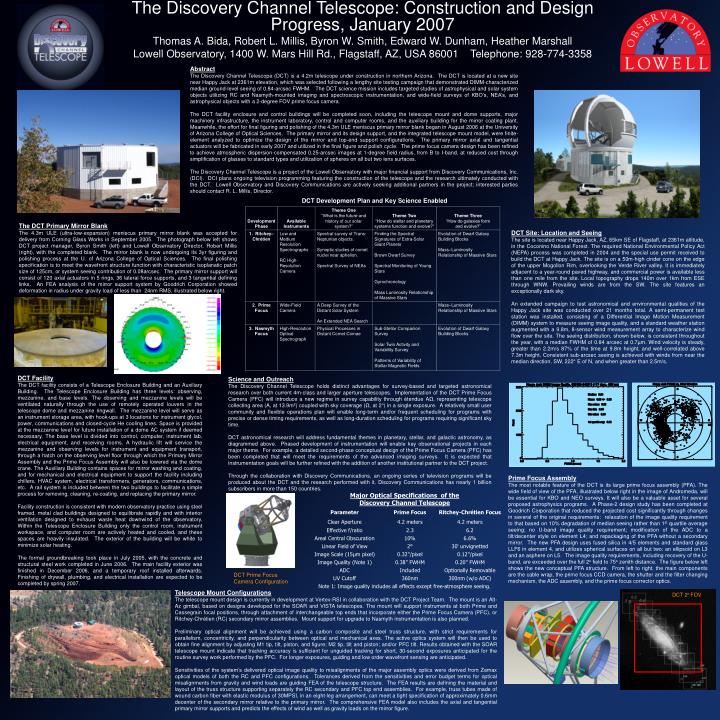
DCT 2o FOV Abstract The Discovery Channel Telescope (DCT) is a 4.2m telescope under construction in northern Arizona. The DCT is located at a new site near Happy Jack at 2361m elevation, which was selected following a lengthy site testing campaign that demonstrated DIMM-characterized median ground-level seeing of 0.84-arcsec FWHM. The DCT science mission includes targeted studies of astrophysical and solar system objects utilizing RC and Nasmyth-mounted imaging and spectroscopic instrumentation, and wide-field surveys of KBO’s, NEA’s, and astrophysical objects with a 2-degree FOV prime focus camera. The DCT facility enclosure and control buildings will be completed soon, including the telescope mount and dome supports, major machinery infrastructure, the instrument laboratory, control and computer rooms, and the auxiliary building for the mirror coating plant. Meanwhile, the effort for final figuring and polishing of the 4.3m ULE meniscus primary mirror blank began in August 2006 at the University of Arizona College of Optical Sciences. The primary mirror and its design support, and the integrated telescope mount model, were finite-element analyzed to optimize the design of the mirror and top-end support configurations. The primary mirror axial and tangential actuators will be fabricated in early 2007 and utilized in the final figure and polish cycle. The prime focus camera design has been refined to achieve atmospheric dispersion-compensated 0.25-arcsec images at 1-degree field radius, from B to I-band, at reduced cost through simplification of glasses to standard types and utilization of spheres on all but two lens surfaces. The Discovery Channel Telescope is a project of the Lowell Observatory with major financial support from Discovery Communications, Inc. (DCI). DCI plans ongoing television programming featuring the construction of the telescope and the research ultimately conducted with the DCT. Lowell Observatory and Discovery Communications are actively seeking additional partners in the project; interested parties should contact R. L. Millis, Director. DCT Development Plan and Key Science Enabled The DCT Primary Mirror Blank The 4.3m ULE (ultra-low-expansion) meniscus primary mirror blank was accepted for delivery from Corning Glass Works in September 2005. The photograph below left shows DCT project manager, Byron Smith (left) and Lowell Observatory Director, Robert Millis (right), with the completed blank. The mirror blank is now undergoing its 3yr figuring and polishing process at the U. of Arizona College of Optical Sciences. The final polishing specification is to meet the wavefront structure function with characteristic isoplanatic patch size of 125cm, or system seeing contribution of 0.08arcsec. The primary mirror support will consist of 120 axial actuators in 5 rings, 36 lateral force supports, and 3 tangential defining links. An FEA analysis of the mirror support system by Goodrich Corporation showed deformation in radius under gravity load of less than 24nm RMS, illustrated below right. DCT Site: Location and Seeing The site is located near Happy Jack, AZ, 65km SE of Flagstaff, at 2361m altitude, in the Coconino National Forest. The required National Environmental Policy Act (NEPA) process was completed in 2004 and the special use permit received to build the DCT at Happy Jack. The site is on a 50m-high cinder cone on the edge of the upper Mogollon Rim, overlooking the Verde River valley. It is immediately adjacent to a year-round paved highway, and commercial power is available less than one mile from the site. Local topography drops 140m over 1km from ESE through WNW. Prevailing winds are from the SW. The site features an exceptionally dark sky. An extended campaign to test astronomical and environmental qualities of the Happy Jack site was conducted over 21 months total. A semi-permanent test station was installed, consisting of a Differential Image Motion Measurement (DIMM) system to measure seeing image quality, and a standard weather station augmented with a 9.8m, 8-sensor wind measurement array to characterize wind flow over the site. The seeing distribution, shown below, is consistent throughout the year, with a median FWHM of 0.84 arcsec at 0.7µm. Wind velocity is steady, greater than 2.2m/s 87% of the time at 9.8m height, and well-correlated above 7.3m height. Consistent sub-arcsec seeing is achieved with winds from near the median direction, SW, 222° E of N, and when greater than 2.5m/s. DCT Facility The DCT facility consists of a Telescope Enclosure Building and an Auxiliary Building. The Telescope Enclosure Building has three levels: observing, mezzanine, and base levels. The observing and mezzanine levels will be ventilated naturally through the use of remotely operated louvers in the telescope dome and mezzanine ringwall. The mezzanine level will serve as an instrument storage area, with hook-ups at 3 locations for instrument glycol, power, communications and closed-cycle He cooling lines. Space is provided at the mezzanine level for future installation of a dome AC system if deemed necessary. The base level is divided into control, computer, instrument lab, electrical equipment, and receiving rooms. A hydraulic lift will service the mezzanine and observing levels for instrument and equipment transport, through a hatch on the observing level floor through which the Primary Mirror Assembly and the Prime Focus Assembly will also be lowered via the dome crane. The Auxiliary Building contains spaces for mirror washing and coating, and for mechanical and electrical equipment to support the facility including chillers, HVAC system, electrical transformers, generators, communications, etc. A rail system is included between the two buildings to facilitate a simple process for removing, cleaning, re-coating, and replacing the primary mirror. Facility construction is consistent with modern observatory practice using steel framed, metal clad buildings designed to equilibrate rapidly and with interior ventilation designed to exhaust waste heat downwind of the observatory. Within the Telescope Enclosure Building only the control room, instrument workspace, and computer room are actively heated and cooled, and these spaces are heavily insulated. The exterior of the building will be white to minimize solar heating. The formal groundbreaking took place in July 2005, with the concrete and structural steel work completed in June 2006. The main facility exterior was finished in December 2006, and a temporary roof installed afterwards. Finishing of drywall, plumbing, and electrical installation are expected to be completed by spring 2007. Science and Outreach The Discovery Channel Telescope holds distinct advantages for survey-based and targeted astronomical research over both current 4m-class and larger aperture telescopes. Implementation of the DCT Prime Focus Camera (PFC) will introduce a new regime in survey capability through étendue AΩ, representing telescope collecting area (A, at 13.9m2) coupled with sky coverage (Ω, at 2°) in a single exposure. A relatively small user community and flexible operations plan will enable long-term and/or frequent scheduling for programs with precise or dense timing requirements, as well as long-duration scheduling for programs requiring significant sky time. DCT astronomical research will address fundamental themes in planetary, stellar, and galactic astronomy, as diagrammed above. Phased development of instrumentation will enable key observational projects in each major theme. For example, a detailed second-phase conceptual design of the Prime Focus Camera (PFC) has been completed that will meet the requirements of the advanced imaging surveys. It is expected that instrumentation goals will be further refined with the addition of another institutional partner to the DCT project. Through the collaboration with Discovery Communications, an ongoing series of television programs will be produced about the DCT and the research performed with it. Discovery Communications has nearly 1 billion subscribers in more than 150 countries. The Discovery Channel Telescope: Construction and Design Progress, January 2007 Thomas A. Bida, Robert L. Millis, Byron W. Smith, Edward W. Dunham, Heather Marshall Lowell Observatory, 1400 W. Mars Hill Rd., Flagstaff, AZ, USA 86001 Telephone: 928-774-3358 Prime Focus Assembly The most notable feature of the DCT is its large prime focus assembly (PFA). The wide field of view of the PFA, illustrated below right in the image of Andromeda, will be essential for KBO and NEO surveys. It will also be a valuable asset for several proposed astrophysics programs. A Phase-2 design study has been completed at Goodrich Corporation that reduced the projected cost significantly through changes in several of the original requirements: relaxation of the image quality requirement to that based on 10% degradation of median seeing rather than 1st quartile average seeing; no U-band image quality requirement; modification of the ADC to a tilt/decenter style on element L4; and repackaging of the PFA without a secondary mirror. The new PFA design uses fused silica in 4/5 elements and standard glass LLF6 in element 4, and utilizes spherical surfaces on all but two: an ellipsoid on L3 and an asphere on L5. The image quality requirements, including recovery of the U-band, are exceeded over the full 2o field to 75o zenith distance. The figure below left shows the new conceptual PFA structure. From left to right, the main components are the cable wrap, the prime focus CCD camera, the shutter and the filter changing mechanism, the ADC assembly, and the prime focus corrector optics. DCT Prime Focus Camera Configuration Telescope Mount Configurations The telescope mount design is currently in development at Vertex-RSI in collaboration with the DCT Project Team. The mount is an Alt-Az gimbal, based on designs developed for the SOAR and VISTA telescopes. The mount will support instruments at both Prime and Cassegrain focal positions, through attachment of interchangeable top ends that incorporate either the Prime Focus Camera (PFC), or Ritchey-Chrétien (RC) secondary mirror assemblies. Mount support for upgrade to Nasmyth instrumentation is also planned. Preliminary optical alignment will be achieved using a carbon composite and steel truss structure, with strict requirements for parallelism, concentricity, and perpendicularity between optical and mechanical axes. The active optics system will then be used to obtain fine alignment by adjusting M1 tip, tilt, piston, and figure; M2 tip, tilt and piston; and/or PFC tilt. Results obtained with the SOAR telescope mount indicate that tracking accuracy is sufficient for unguided tracking for short, 30-second exposures anticipated for the routine survey work performed by the PFC. For longer exposures, guiding and low order wavefront sensing are anticipated. Sensitivities of the system’s delivered optical image quality to misalignments of the major assembly optics were derived from Zemax optical models of both the RC and PFC configurations. Tolerances derived from the sensitivities and error budget terms for optical misalignments from gravity and wind loads are guiding FEA of the telescope structure. The FEA results are defining the material and layout of the truss structure supporting separately the RC secondary and PFC top end assemblies. For example, truss tubes made of wound carbon fiber with elastic modulus of 30MPSI, in an eight-leg arrangement, can meet a tight specification of approximately 0.6mm decenter of the secondary mirror relative to the primary mirror. The comprehensive FEA model also includes the axial and tangential primary mirror supports and predicts the effects of wind as well as gravity loads on the mirror figure.