Download
1 / 48
530 likes | 802 Vues
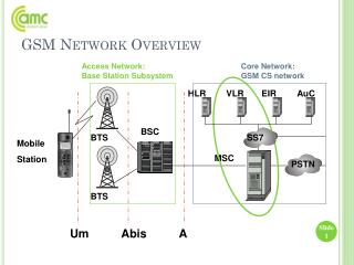
GSM Overview. Manish singh. OBJECTIVES. Describe the Cellular Concept Explain the GSM Access Network Explain the GSM Core Network Explain the GPRS Core Network. Inter-Exchange Junction. Subscriber Line (2W). BSC. BTS. MS. Telephone Exchange. Mobile Switching Centre (MSC).

E N D
GSM Overview Manish singh
OBJECTIVES • Describe the Cellular Concept • Explain the GSM Access Network • Explain the GSM Core Network • Explain the GPRS Core Network
Inter-Exchange Junction Subscriber Line (2W) BSC BTS MS Telephone Exchange Mobile Switching Centre (MSC) Communication - Mobile
CELLULARMOBILECONCEPTS WHAT IS A CELL ? • A base station (transmitter) having a number of • RF channels is called a cell • Each cell covers a a limited number of mobile • subscribers within the cell boundaries • ( Coverage area) • Typical Cell Radius Aprrox = 30 Km • (Start up), 1 KM (Mature)
Voice Channels Coverage area Forward path Reverse path Or control channels MS Lines to BSC A RADIO CELL
Large no. of subscribers in the range of millions Fundamental problems • Radio range, or coverage • No. of channels, or voice circuits • Full, seamless service coverage
GSM Specifications Carrier Separation - 200 kHz Duplex Distance - 45 MHz No. of RF Carriers - 124 Access Method - TDMA/FDMA Modulation Method - GMSK Transmission Rate - 270.833 Kbps Speech Coding - Full rate 13 Kbps Half rate 6.5 Kbps
890 915 935 960 25 MHz 25 MHz 1 2 1 2 0 0 Mobile to Base Base to Mobile (MHz) 890.4 890.6 935.4 935.6 890.2 935.2 200 kHz 200 kHz 45MHz Channel layout and frequency bands of operation GSMFDMA(Frequency Division Multiple Access
8 8 7 7 6 6 5 5 4 4 3 3 2 2 1 1 GSMTDMA(Time Division Multiple Access) Amplitude 45 MHz Frequency F1 (Cell Rx) F2 F2’ F1’ (Cell transmit) Typical TDMA/ FDMA frame structure
TIME BP2 BP1 BP8 BURST BP7 BP6 BP5 BP4 BP3 BP2 BP1 FREQ MHz 890.2 890.6 891.0 915.8 890.0 890.4 890.8 891.2 FDMA/TDMA Scheme F R A M E
GSM RF CHANNELS LOGICAL CHANNELS • USER INFORMATION( TRAFFIC) • SIGNALLING INFORMATION (CONTROL)
OPERATIONAL CONCEPTS • Subscribers are not allocated dedicated channels • TCH Allocated to users only when needed • Hence IDLE MODE & DEDICATED MODE • DEDICATED MODE -- When a full Bi -directional P to P CHL has been allocated during an established call • IDLE MODE MODE -- When MS is powered on (active) without being in dedicated mode
B T S B T S MSC VLR B T S MSC VLR Network Architecture 1 MSC=16 BSC 1 BSC=1024 TRU OSS ( HLR PSTN ISDN Data Networks BSC A Interface A-bis interface Air interface
GSM Service Area:Total area served by the combination of all member countries where a mobile can be served. PLMN Service Area:It is one N/W area. MSC Service Area:There can many MSC/VLR in one PLMN area.It is one Mobile Exch. Area. GMSC:All I/C calls for PLMN N/W will be routed through GMSC. In a GSM/PLMN N/W all mobile terminated calls will be routed to a Gateway MSC. Call connections between PLMNs , or to fixed N/Ws must be routed to a GMSC.The GMSC contains the Inter working functions to make these connections. Location Area Cells GSM Network Structure
GSM Network Structure LOCATION AREA :There are several LA in a MSC/VLR combination. A LA is a part of the MSC/VLR service area in which a MS may move freely without updating location information to the MSC/VLR exchange that control the LA. Within a LA a paging message is broadcast in order to find the called mobile subs. LA can be identified by system using the LAI. CELL :A cell is an identity served by one BTS. The MS distinguishes between cells using the BASE STATION IDENTIFICATION CODE(BSIC) that the cell site broadcast over the air.
MSC/VLR MSC/VLR MSC/VLR MSC/VLR I II IV III GSMPLMN Service Area
MSC/VLR LA 2 LA 1 LA 3 LA 6 LA 4 LA 5 GSMMSC Service Area
MSC/VLR GSMCells C1 LA 3 LA 2 LA 1 C2 C6 C4 C5 C3 C7 LA 6 LA 4 LA 5 C = Cell
Location Area Cell Area served by a BTS Location Area MSC Service Area PLMN Service Area GSM Service Area GSMRelation between areas in GSM
Voice and data transmission Frequency and time synchronization Monitoring of power and signal quality of the surrounding cells Provision of location updates even during inactive state Equalization of multi path distortions GSMFunctions of Mobile Station
Portable, vehicle mounted, hand held MS identified by unique IMEI(International Mobile Equipment Identity) Shall display at least last ten received, dialled and missed calls Minimum talk time of 1hr 30 min. and standby time of 80 hrs 160 characters long SMS GSMMobile Station
IMEI MSISDN IMSI GSMMobile Identification Numbers
International mobile subscriber’s Identity The IMSI is an unique identity which is used internationally and used within the network to identify the mobile subscribers. The IMSI is stored on the subscriber identity module (SIM), the HLR, VLR and AC database. GSMIMSI
MSC/VLR BSC BSC BSC n BTS n BTS RADIO SUB SYSTEM (RSS) RSS
Encodes, encrypts, multiplexes, modulates and feeds the RF signals to the antenna Transcoding and rate adaption Functionality Time and frequency synchronisation signals transmission. GSMFUNCTION OF BTS -I
Frequency hopping Random access detection Uplink radio channel measurements BTS mainly consists of a set of transceivers (TRX). GSMFUNCTION OF BTS -II
It is connected to BTS and offloads MSC Radio resource management Inter-cell handover Reallocation of frequencies Power control GSMFUNCTIONS OF BSC-I
Time delay measurement of the received signals from MS with respect to BTS clock. Performs traffic concentration to reduce the number of lines from BSC to MSC. GSMFUNCTIONS OF BSC-II
BTS BSS BTS BTS BTS BTS BTS MSC BTS BSC GSMMSC-BSS Configurations Multi - cell site (sector Cells Configuration -5 A A Single - cell site Configuration -1 A Many single cell sites BSS A-bis A-bis Multi - cell site = multi--BTS site Configuration -6 MCC: Mobile Switching Centre BSS: Base Station System BSC: Base Station Controller BTS: Base Transceiver Station
Manages communication between GSM & other network Call setup functions, basic switching are done MSC takes into account the RR allocation in addition to normal exchange functions MSC does gateway function while its customers roams to other network by using HLR /VLR GSMMSC ( MOBILE SWITCHING CENTRE)
Paging, specifically call handling Location updation Handover management Billing for all subscribers based in its area Reallocation of frequencies to BTSs in its area to meet heavy demands GSMMSC Functions - I
Echo canceller operation control Signaling interface to databases like HLR, VLR. Gateway to SMS between SMS centers and subscribers Handle interworking function while working as GMSC GSMMSC Functions - II
It controls those mobiles roaming in its area. VLR reduces the number of queries to HLR One VLR may be incharge of one or more LA. VLR is updated by HLR on entry of MS its area. VLR assigns TMSI which keeps on changing. IMSI detach and attach operation GSMVISITOR LOCATION REGISTER (VLR)-I
IMSI & TMSI MSISDN MSRN. Location Area Supplementary service parameters MS category Authentication Key GSMData in VLR
Reference store for subscriber’s parameters, numbers, authentication & Encryption values. Current subscriber status and associated VLR. Both VLR and HLR can be implemented in the same equipment in an MSC. one PLMN may contain one or several HLR. GSM Home Location Register(HLR)-I
Data stored is changed only by man-machine. IMSI, MS-ISDN number. Category of MS ( whether pay phone or not ) Roaming restriction ( allowed or not ). Supplementary services like call forwarding GSM Home Location Register(HLR)-II Permanent data in HLR
Temporary data in HLR The data changes from call to call & is dynamic MSRN RAND /SRES and Kc VLR address, MSC address. Messages waiting data used for SMS GSM Home Location Register(HLR)-II
SMS-G/IW MSC BSC MSC/VLR HLR AUC BTS MS EDGE TRU Iu MS MS UMTS R N C BTS U T R A N BTS R N C BTS Network Evolution Gd P C U Gs Gr ISP Network Gb SGSN GGSN Gi Gn Gn CorporateNetwork Backbone Network
SMS-G/IW MSC BSC MSC/VLR HLR AUC BTS MS EDGE TRU MS Network Evolution Gd P C U Gs Gr ISP Network Gb SGSN GGSN Gi Gn Gn CorporateNetwork Backbone Network
SMS-G/IW MSC BSC MSC/VLR HLR AUC BTS MS EDGE TRU Iu MS MS UMTS R N C BTS U T R A N BTS R N C BTS Network Evolution Gd P C U Gs Gr ISP Network Gb SGSN GGSN Gi Gn Gn CorporateNetwork Backbone Network
GPRS Architecture BTS ISDN / PSTN / PLMN Network GMSC MSC/VLR Um MT Abis EIR A BSC Gs AUC Gf TE SGSN MS Gb HLR BSS Gr IP-Backbone Network Gn A GSM Interface Abis GSM Interface (Proprietary of M/s Ericsson) AUC Authentication Center BSC Base Station Center BSS Base Station System BTS Base Transceiver Station EIR Equipment Identity Register GGSN Gateway GPRS Support Node GMSC Gateway Mobile services Switching Center Gx GPRS Interfaces HLR Home Location Register MS Mobile Station MSC Mobile services Switching Center MT Mobile Terminal SGSN Serving GPRS Support Node TE Terminal Equipment Um Air Interface VLR Visitor Location Register Gn Gi GGSN External IP Network Gi External X.25 Network GSM Network Elements Signaling GPRS Network Elements Traffic & Signaling
To ensure the interworking of the PLMN, PDN and the wireless networks, two new major components are required. These components are called GPRS Support Nodes. There are two types of GPRS Support Nodes Serving GPRS Support Node (SGSN) Gateway GPRS Support Node (GGSN) GPRS COMPONENTS
An SGSN delivers packets to mobile stations within its service area. SGSNs send queries to Home Location Registers (HLRs) to obtain profile data of GPRS subscribers. SGSNs detect new GPRS mobile stations in a given service area; and, finally, SGSNs process registration of new mobile subscribers and keep a record of their location inside a given service area. Serving GPRS Support Node (SGSN)
GGSNs are used as interfaces to external PDNs. GGSNs maintain routing information that is necessary to tunnel the Protocol Data Units (PDUs) to the SGSNs that service particular mobile stations. Other functions include network and subscriber screening and address mapping. One or more GGSNs may support multiple SGSNs. Gateway GPRS Support Node(GGSN)
In addition to the new GPRS components, existing GSM and TDMA network elements must also be enhanced in order to support GPRS. The following two pieces of equipment must be enhanced: Base Station System (BSS): must be enhanced to recognize and send user data to the SGSN that is serving the area. Home Location Register (HLR): must be enhanced to register GPRS user profiles and respond to queries originating from SGSNs regarding these profiles. GPRS Network Enhancements
Increased revenues by moving in to the mobile data market Gain new subscribers requiring the data services without investing in to PCs to gain internet access Retain current subscribers by offering new services Reduce costs due to efficient use of network resources Advantages of GPRS