Download
1 / 1

E N D
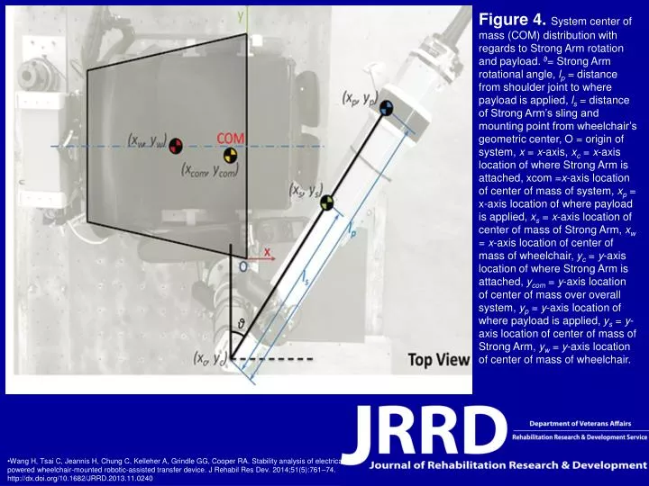
Figure 4. System center of mass (COM) distribution with regards to Strong Arm rotation and payload. ϑ= Strong Arm rotational angle, lp = distance from shoulder joint to where payload is applied, ls = distance of Strong Arm’s sling and mounting point from wheelchair’s geometric center, O = origin of system, x = x-axis, xc = x-axis location of where Strong Arm is attached, xcom =x-axis location of center of mass of system, xp = x-axis location of where payload is applied, xs = x-axis location of center of mass of Strong Arm, xw = x-axis location of center of mass of wheelchair, yc = y-axis location of where Strong Arm is attached, ycom = y-axis location of center of mass over overall system, yp = y-axis location of where payload is applied, ys = y-axis location of center of mass of Strong Arm, yw = y-axis location of center of mass of wheelchair. • Wang H, Tsai C, Jeannis H, Chung C, Kelleher A, Grindle GG, Cooper RA. Stability analysis of electrical powered wheelchair-mounted robotic-assisted transfer device. J Rehabil Res Dev. 2014;51(5):761–74.http://dx.doi.org/10.1682/JRRD.2013.11.0240