Download
1 / 74
760 likes | 961 Vues
SFAR 88/Related Operating Rules Special Maintenance Requirements & Compliance Planning Briefing. Operators, FAA Inspectors and Engineers November 7, 2002 Presented by: Mario L. Giordano, FAA Continuous Airworthiness Maintenance Division, Senior Advisor, AFS-303

E N D
SFAR 88/Related Operating RulesSpecial Maintenance Requirements &Compliance Planning Briefing Operators, FAA Inspectors and Engineers November 7, 2002 Presented by: Mario L. Giordano, FAA Continuous Airworthiness Maintenance Division, Senior Advisor, AFS-303 Michael Zielinski, FAA Transport Airplane Directorate, AFS Liaison Program Manager, ANM-105
Service History Summary • Since 1959 there have been 17 fuel tank ignition events, resulting in: • 542 fatalities, • 11 hull losses • 3 others with substantial damage • Causes: • 3 unknown • 4 caused by external wing fires • 4 electrostatics • 2 lightning • 2 pumps or wiring suspected • 1 by small bomb • 1 maintenance action.
Historical review • MILITARY - 12 hull loss accidents on military version of B-707 and B52 airplanes • All tanks fueled with higher volatility JP-4 fuel • Military has converted to low volatility JP-8 • 10 of 12 occurred in body or center wing tanks • 7 occurred on ground during refueling or maintenance • 5 in flight - specific cause not identified in many incidents- pumps and fuel quantity indicating system (FQIS) wiring suspected • Military has imposed new dry run requirements on pumps
KEY COMMERCIAL ACCIDENT SPECIFICS • 1963 - B-707 Elkton Maryland • 3 year old airplane • Empty wing tank explosion • JP-4 fuel, approx. 95 degree F ambient temp. • 81 fatalities • Lightning strike during decent • 1970 - DC-8 Toronto Canada • Less than 5 year old airplane • JP-4 fuel • 106 fatalities • External fuel fire caused tank explosion
KEY COMMERCIAL ACCIDENT SPECIFICS • 1974 - B-747-100 Spain- Iranian Air Force • 3 year old airplane • Empty wing tank explosion • Lightning strike during decent • 8 fatalities • JP-4 fuel, approx. 95 degree F ambient temp. • NO IGNITION SOURCE IDENTIFIED - Three airworthiness directives (AD) issued • 1989 - B-727-Bogata Columbia • Empty CWT explosion during climb • Small bomb placed in carry on in passenger cabin causes tank explosion • 107 fatalities • Jet-A fuel, approx. 95 degree F ambient temp.
KEY COMMERCIAL ACCIDENT SPECIFICS • 1990 - B-737-300 Manila, Philippine • Almost new airplane • Empty CWT explosion during pushback from gate • CWT pumps operating at time of explosion • 8 fatalities • Jet-A fuel, approx. 95 degree F ambient temp. • NO IGNITION SOURCE IDENTIFIED • 1996 - B-747, TWA 800, JFK • 25 year old airplane • Empty CWT explosion during climb • 230 fatalities • Jet-A fuel, approx. 120 degree F tank temp. • NO IGNITION SOURCE IDENTIFIED however, the NTSB believes the likely energy source was a short circuit outside of the CWT the allowed excessive voltage to enter the CWT through the FQIS wiring. Also the NTSB believes that a contributing factor may have been a heat source from the air conditioning systems located below the CWT.
KEY COMMERCIAL ACCIDENT SPECIFICS • 2001 - B-737-400 Bangkok Thailand • 10 year old airplane • Empty CWT explosion minutes after refueling • CWT pumps operating at time of explosion • 1 fatality • Jet-A1 fuel, approx. 97 degree F ambient temp. • NO IGNITION SOURCE IDENTIFIED
Fuel System Safety Compliance Data June 6, 2001 SFAR 88 Rule became effective. Applicable TC, STC holders have compliance date of December 6, 2002 Phase One SFAR Rule Implementation June 6, 2001 FAR Parts 25, 91, 121, 125, 129 amended to require instructions for maint. and inspection of the fuel tank system be incorporated into the operators Maint. Program and be FAA approved by June 7, 2004 Phase Two FAR Rule Implementation
PART 21 -”Certification Procedures for Products and Parts”Summary • Part 21 - Certification Procedures • New Special Federal Aviation Regulation (SFAR) • Applies to “the holders of type certificates, and STCs that may affect the fuel tank system of turbine powered transport category airplanes” • 30 passengers or more or • 7500 lbs payload or more, certified after 1/1/58 • Requires fleet review of fuel tank system designs • Addresses lessons learned • Demonstrate design precludes ignition sources • Develop all design changes necessary to meet requirements • Develop all necessary maintenance and inspection instructions • Submit a report to ACO • Compliance time is 18 months after the effective date of the final rule • For existing certification projects, 18 months after certification date or 18 months after SFAR effective date, whichever is later
Part 25 - Airworthiness StandardsAmendment 25-102 • Amended § 25.981 Ignition Prevention Requirements • New § 25.981(a) & (b) apply to SFAR 88 • Maintains existing Autoignition Requirements • Adds explicit requirements for analysis to demonstrate the design precludes failures that can cause ignition sources • Includes a design review (system safety analysis) requirement • Maintains powerplant regulation philosophy of considering latent failures • Requirement for Instructions for Continued Airworthiness
Amendment 25-102(Continued) • New § 25.981(c) Flammability Requirement • Minimize development of flammable vapors, OR • Mitigate effects of ignition of flammable vapors • Based on ARAC recommendation • Applies to new designs changes • Does NOT apply to SFAR 88 design reviews Note: SFAR 88 amendment issued Sept. 10, 2002 allows equivalent safety provisions for fuel tank system fault tolerance evaluations. If an aircraft were equipped with a fuel tank “inerting” system, it could mitigate some of the ignition prevention requirements of SFAR88.
Amendment 25-102(Continued) • Part 25, Appendix H (H25.4) Airworthiness Limitations section. • Requires including fuel tank safety limitations in the Instructions for Continued Airworthiness. • Revised Appendix H applies to new type design changes through the existing § 21.50, “Instructions for continued airworthiness and manufacturer’s maintenance manuals having airworthiness limitations sections.”
ICAs • Revised Appendix H to Part 25 - Instructions for Continued Airworthiness • (a) The Instructions for Continued Airworthiness must contain a section titled Airworthiness Limitations that is segregated and clearly distinguishable from the rest of the document. This section must set forth-- • (1) Each mandatory replacement time, structural inspection interval, and related structural inspection procedures approved under Sec. 25.571; and • (2) Each mandatory replacement time, inspection interval, related inspection procedure, and all critical design configuration control limitations approved under Sec. 25.981 for the fuel tank system.
ICA’s – cont’d • Not CMR’s • The concept of this rule goes beyond the current CMR process. CMR's only address mandatory maintenance that is applied to the airplane at the time of original certification. The requirement of this rule for configuration design control limitations will address not only MANDATORY maintenance actions, but also design features that cannot be ALTERED except in accordance with the Instructions for Continued Airworthiness (ICA).
Critical Design Configuration Control Limitations (CDCCL) • Defined by design approval applicants subject to SFAR 88 • Features of an airplane design, such as wire separation, explosion proof features of a fuel pump, maintenance intervals for transient suppression devices, minimum bonding jumper resistance levels, etc., where any maintenance actions or subsequent changes to the product made by operators or the manufacturer MUST NOT DEGRADE the level of safety of the original type design. Note: The definition of critical design configuration control limitations does not include ``all of the features inherent'' in the design; it only includes information that is necessary to ensure safety of fuel tank systems.
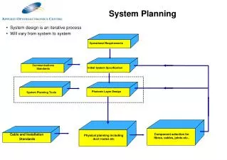
Fuel System Limitations (FSLs) Certificate holders propose maintenance and inspection (M&I) instructions and configuration control (CDCCL) requirements FAA Aircraft Certification Reviews and approves FAA Flight Standards approves means for incorporation Operator proposes M&I and CDCCL for “Actual Configuration” 19
Fuel System Limitations (FSLs) • Industry established the FSL term for clarity/segregation. • All FSLs are Airworthiness Limitations Items derived from safety review: • contains the instructions for maintenance and inspection of the fuel tank SYSTEM, including initial and repetitive inspection frequencies, required instruments, pass/fail criteria, etc. and • any applicable critical design configuration control limitations • Operator’s FSLs for a specific aircraft model will include: • OEM/STC FSLs (where applicable) • Major alteration, field approval, etc. FSLs (where applicable) • All affected OEM FSLs will be clearly identified and listed in an applicable manufacturer’s Maintenance Program Document, such as the Boeing MPD, Section 9.
FSLs - cont’d • Affected operator’s submit FSLs through the Principal Inspectors prior to submittal to FAA Aircraft Certification for review and approval. • The Operator’s Maintenance Program must identify FAA Aircraft Certification approved FSL applicability for EACH specific aircraft contained in the Operator’s Aircraft Listing (D085). • All FAA Aircraft Certification approved FSLs must have operator work instructions (Job Cards, Task Cards, Aircraft Maintenance Manual (AMM) procedures) completed and submitted to the Principal Inspectors for review PRIOR to Operations Specifications approval by June 7, 2004.
FSLs - cont’d • All operators must have tooling/training requirements completed prior to actual accomplishment of FSLs. Note: In addition to new maintenance and inspection tasks, it is likely that some of the present fuel tank system zonal inspection items using the General Visual Inspection (GVI) technique will become FSLs requiring Detailed Visual Inspections (DVIs). Some DVIs may require a one time fleetwide conformity inspection and/or accelerated inspection frequencies.
Related Guidance Information • AC’s available on the web • http://www.faa.gov/avr/air/acs/achome.htm • AC 25.981-1c: Fuel Tank Ignition Source Prevention Guidelines • Acceptable method for demonstrating compliance with ignition prevention requirements • Including demonstrating compliance with the SFAR design review • Includes a listing of lessons learned • AC 25.981-2: Fuel Tank Flammability Minimization • Acceptable method for the demonstrating compliance with fuel tank flammability requirements • FAA drafting guidance on expected content of FSLs and the roles and responsibilities of the ACOs, AEGs and Flight Standards principal inspectors. 23
Special Maintenance Program Requirements • Rules Amended • 91.410(b), 121.370(b), 125.248(b) and 129.32(b) • Applicability • turbine-powered transport category airplanes • type certificate issued after January 1, 1958, • either a maximum type certificated passenger capacity of 30 or more, or a maximum type certificated payload capacity of 7,500 pounds or more
Sec. 121.370 Special maintenance program requirements. • (b) After June 7, 2004, no certificate holder may operate a turbine-powered transport category airplane ..., unless instructions for maintenance and inspection of the fuel tank system are incorporated in its maintenance program. These instructions must address the actual configuration of the fuel tank systems of each affected airplane and must be approved by the FAA Aircraft Certification Office (ACO/TAD) ... Operators must submit their request through an appropriate FAA Principal Maintenance Inspector, who may add comments and then send it to the manager of the appropriate office. Thereafter, the approved instructions can be revised only with the approval of the FAA Aircraft Certification Office (ACO/TAD)... Operators must submit their requests for revisions through an appropriate FAA Principal Maintenance Inspector, who may add ... 25
Special Maintenance Requirements • Instructions for maintenance and inspection (a.k.a. instructions for continued airworthiness (ICA) of the fuel tank system are required to be incorporated in the operator’s maintenance program by June 7, 2004. • ICA determination based on design review of the fuel tank system • ICAs approved by ACO • Possible design changes • Mandatory inspection/maintenance tasks Note: The system may include items pertaining to other areas such as pneumatics and air conditioning.
Special Maintenance Requirements Driven by the Design Review • The design review is a failure modes and effects analysis that considers “multiple failures” • Excerpt from § 25.981 Fuel tank ignition prevention Amendment 102 • Demonstrating that an ignition source could not result from each single failure, from each single failure in combination with each latent failure condition not shown to be extremely remote, and from all combinations of failures not shown to be extremely improbable. • MRB use of MSG-3 • Considers only hidden plus one • MRB use of MSG-2 • Considers only single failures • Not 25.1309 Vs.
Special Maintenance Requirements ACO Approved • Why? • Because of the required design review • FAA engineering expertise required to review and approve acceptability of analysis • Type Certificate (TC) and Supplemental Type Certificate Holders (STC) Holders • Interaction of Multiple Configurations • 35 transport category models affected • 600 plus STCs highly likely to be impacted (Category 1) (see website http://www.faa.gov/certification/aircraft/SFAR88/stc-list.cfm) • 20,000 plus STCs less likely to be impacted (Category 2) • Operator and/or Airplane specific “actual configuration”
Design Review • The level of evaluation that is intended depends upon the basic design and type of modification. In most cases a simple QUALITATIVE evaluation of the design/modification in relation to fuel tank system safety, and a statement to the cognizant ACO that the change has no effect on the fuel tank system safety, would be all that is necessary. In other cases where the initial qualitative assessment shows that there may be an affect on fuel tank system safety, A MORE DETAILED DESIGN review would be required to substantiate that the airplane fuel tank system design/modifications, including all necessary design changes, meets the requirements of §§ 25.901 and 25.981(a) and (b).
Analysis Considerations • QUALITATIVE ANALYSIS - Analytical processes that assess system and airplane safety in a subjective non-numerical manner, e.g., development of flightcrew procedures to mitigate inflight failure conditions • QUANTITATIVE ANALYSIS - Analytical processes that apply mathematical methods to assess system and airplane safety, e.g., using failure rate probabilities to determine safety risk
Compliance Planning • TC and STC Holders’ Responsibilities • Operators’ Responsibilities • Principal Inspectors’ Overview and Responsibilities
Compliance Planning TC/STC Holders • Provide design review report by 12/6/2002 to ACO that includes: • Design changes NECESSARY to comply with SFAR • Identification of safety CRITICAL fuel tank system design features. • Identification of the appropriate marking for those features so future maintenance actions do not DEGRADE the intended level of safety. • ALL maintenance and inspection instructions necessary to maintain the design features required to preclude the existence or development of an ignition source within the fuel tank system throughout the operational life of the airplane • COMPARABILITY of design review required inspection and maintenance • COMMUNICATE with operators regarding progress of the design review and probable outcomes
STC Holders Dependency on OEM • STC holders may not have access to information from respective OEM’s • Basic OEM system descriptions, wiring diagrams and/or the OEM’s limitations • Lacking this information, STC holders may not be able to determine what are the OEM’s critical systems • STC holders may therefore be unable to compile a complete SSA for their installation.
Completing STC Reviews • For Example: • STC holders conducting a SSA concerning the possible effects of their STC wiring on the fuel tank system safety have three options.
Completing STC Reviews • Option 1: • Work with the OEM to determine what modifications to the airplanes will be made to provide fail-safe features • In many cases transient suppression devices will be developed & installed • This would facilitate the SSA for the STC wiring • Critical Design Configuration Control Limitation (CDCCL) information would be available from the OEM so that a complete evaluation would be possible
Completing STC Reviews • Option 2: • Assume that wiring may be routed with critical fuel system wiring (even though no knowledge of what is critical) • STC holder’s submittal might include a statement that the STC wiring exceeds intrinsically safe energy/current levels • Describe voltage and current levels (Normal/Failure) • Wire is installed in accordance with standard wiring practices • i.e. it may not be separated from fuel tank system wires • State the subject wire must be installed and maintained in accordance with CDCCLs & FSL defined by the OEM
Completing STC Reviews • Option 3: • Complete SSA for the STC installation at least to the OEM’s interface. • Then, provide the following limitation, along with any other appropriate limitation(s) for their STC: “This STC complies with Special Federal Aviation Regulation No. 88 when installed in accordance with all critical design configuration control limitations approved by the FAA for this STC and for the airplane model(s) listed in this STC” • This type of limitation will allow STC holders to proceed with their SFAR 88 package submittal
Design Review - Items That May Be Missed • Not a 25.1309 analysis • Latent failures must be combined with single failures unless the latent failure probability, considering exposure time and failure rate, is extremely remote (10-7). • Assumptions: • Environmental conditions must be considered to be present (P=1 on a per flight basis). These include lightning, HIRF, etc. • Fuel tank and adjacent spaces (e.g. leading and trailing edge, wheel well, pack bays etc.) contain flammable vapor, • Foreign object debris (FOD) exists in rotating parts of pumps • Undetected FOD exists on fuel tank electrical sensors and circuits (e.g., FQIS probes, etc. ) • Analysis must consider the operational life of the airplane models, and not just the design life. This was discussed in the preamble to the final rule. (e.g., Long range airplane typically have a life in excess of 100,000 flight hours)
Other Considerations • The effects of manufacturing variability, aging, wear, corrosion, and likely damage must be considered. • OEM is responsible for validating vendor analyses. • Any safety claims for LRUs must be substantiated. • Consider hazards of sulfur deposits. • All fuel tank components should be evaluated for silver content. • Assumptions should be based on overall Lessons Learned by the transport airplane fleet, as stated in the preamble. Lessons Learned should include information from all transport airplane manufacturers experience that is available (e.g., fuel pump ). Available sources of Lessons Learned include AC 25.981-1B, the preamble to SFAR 88 and Airplane Fuel System Safety Program report.
Other Considerations - (cont’d) • Separation and Shielding Approach: • Protecting internal fuel tank wiring by separating and shielding wires and circuits outside the fuel tank would require a one time inspection/replacement of fleet wire configuration and condition (all airplanes). • Routing some fuel tank wires together with 115v and/or 28v wires is not acceptable for a separation and shielding approach. • Visible means should be applied to identify wire separation requirements on airplanes (critical design configuration control limitations). • Separation must also be substantiated and maintained in all components parts of the system, including Line Replaceable Units (e.g. FQIS processor etc). • Means to assure maintenance errors, such as omission of a bonding strap must be addressed. • Consider use of transient suppression devices at or near the fuel tank connections that would eliminate need for one time inspection and rerouting of airplane wires.
Other Considerations - (cont’d) • Electrical: • The FAA believes a redundant bond path will likely be required to address the requirements of the SFAR. OEMs should provide a failsafe bonding design. • In some cases electrical bonding jumpers can fail due to corrosion. • For electrical or electronic systems that introduce electrical energy into fuel tanks, such as fuel quantity indicating systems, the energy introduced into any fuel tank should be less than 200 microjoules during either normal operation or operation with failures. To ensure that the design has adequate reliability and acceptable maintenance intervals, a factor of safety should be applied to this value when establishing a design limit. For example, a maximum energy of 20 microjoules is considered an intrinsically safe design limit for fuel quantity indicating systems.
Other Considerations - (cont’d) • Fuel Pumps • Dry Running: The existing design, including collector boxes and auto-shutoff features on some airplane models provides some protection from mechanical spark ignition; however, some designs still permit dry running of pumps which does not meet the requirements of the SFAR. • Based upon past experience of fuel pump power supply and internal arcing events, the FAA believes protective means will likely be needed on all fuel pumps to satisfy the requirements of the SFAR. • Pneumatic Systems • Potential heat sources adjacent to fuel tanks, i.e., air cycle machine, heat exchanger, associated ducting, etc.
Listing of Deficiencies • Basis: • The following list summarizes fuel tank system design deficiencies, malfunctions, failures, and maintenance-related actions that have been determined through service experience to result in a degradation of the safety features of airplane fuel tank systems. This list was developed from service difficulty reports and incident and accident reports. • These anomalies occurred on 990 in-service transport category airplanes operated by 160 carriers despite regulations, policies, current maintenance and inspection programs in place to preclude the development of ignition sources within airplane fuel tank systems.
Listing of Deficiencies - cont’d • Pumps: • Ingestion of the pump inducer into the pump impeller and generation of debris into the fuel tank. • Pump inlet case degradation, allowing the pump inlet check valve to contact the impeller. • Stator winding failures during operation of the fuel pump. Subsequent failure of a second phase of the pump resulting in arcing through the fuel pump housing. • Deactivation of thermal protective features incorporated into the windings of pumps due to inappropriate wrapping of the windings. • Omission of cooling port tubes between the pump assembly and the pump motor assembly during fuel pump overhaul. • Extended dry running of fuel pumps in empty fuel tanks, which was contrary to the manufacturer's recommended procedures. 46
Listing of Deficiencies - (cont’d) • Pumps: cont’d • Use of steel impellers that may produce sparks if debris enters the pump. • Debris lodged inside pumps. • Arcing due to the exposure of electrical connections within the pump housing that have been designed with inadequate clearance to the pump cover. • Thermal switches resetting over time to a higher trip temperature. • Flame arrestors falling out of their respective mounting. • Internal wires coming in contact with the pump rotating group, energizing the rotor and arcing at the impeller/adapter interface. • Poor bonding across component interfaces. • Insufficient' ground fault current protection capability. • Poor bonding of components to structure. 47
Listing of Deficiencies - (cont’d) • Wiring to pumps in conduits located inside fuel tanks: • Wear of Teflon sleeving and wiring insulation allowing arcing from wire through metallic conduits into fuel tanks. • Fuel pump connectors: • Electrical arcing at connections within electrical connectors due to bent pins or corrosion. • Fuel leakage and subsequent fuel fire outside of the fuel tank caused by corrosion of electrical connectors inside the pump motor which led to electrical arcing through the connector housing (connector was located outside the fuel tank) • Selection of improper materials in connector design. • FQIS wiring: • Degradation of wire insulation (cracking), corrosion and sulfide deposits at electrical connectors • Unshielded FQIS wires routed in wire bundles with high voltage wires. 48
Listing of Deficiencies - (cont’d) • FQIS Probes: • Corrosion and sulfide deposits causing reduced breakdown voltage in FQIS wiring. • Terminal block wiring clamp (strain relief) features at electrical connections on fuel probes causing damage to wiring insulation. • Contamination in the fuel tanks causing a reduced arc path between FQIS probe walls (steel wool, lock wire, nuts, rivets, bolts; or mechanical impact damage to probes) . 49
Listing of Deficiencies - (cont’d) • Bonding straps: • Corrosion to bonding straps. • Loose or improperly grounded attachment points. • Static bonds on fuel tank system plumbing connections inside the fuel tank worn due to mechanical wear of the plumbing from wing movement and corrosion. • Electrostatic charge: • Use of non-conductive reticulated polyurethane foam that holds electrostatic charge buildup. • Spraying of fuel into fuel tanks through inappropriately designed refueling nozzles or pump cooling flow return methods. 50