Download
1 / 43
430 likes | 569 Vues
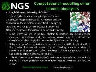
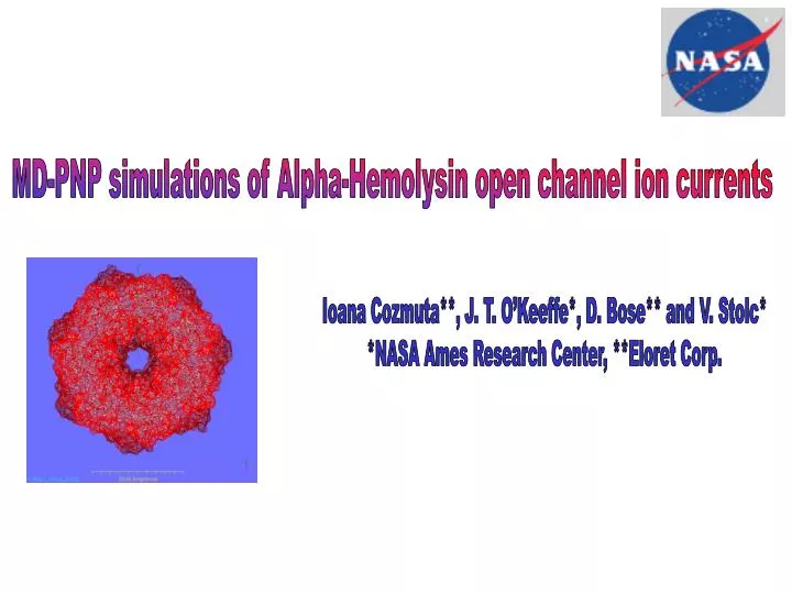
MD-PNP simulations of Alpha-Hemolysin open channel ion currents. Ioana Cozmuta**, J. T. O’Keeffe*, D. Bose** and V. Stolc* *NASA Ames Research Center, **Eloret Corp. The alpha hemolysin ion channel. ‘Natural’ function *. Alpha hemolysin is a toxin produced by Staphylococcus aureus bacteria

E N D
MD-PNP simulations of Alpha-Hemolysin open channel ion currents Ioana Cozmuta**, J. T. O’Keeffe*, D. Bose** and V. Stolc* *NASA Ames Research Center, **Eloret Corp.
‘Natural’ function* • Alpha hemolysin is a toxin produced by Staphylococcus aureus bacteria • It spontaneously self-assembles into a water soluble ionic channel with a molecular weight of 33.2 k-Dalton and a length of ~ 10nm • The channel contains 2051 AA residues organized in 7 sequence-identical chains (symmetry group C121) • The channel is strongly surface active and it inserts into pre-formed lipid membranes, damaging the membrane properties • Extra cellular Ca2+ or other divalent cations prevent cell damage by closing the channel * Menestrina, G, The Journal of Membrane Biology, 90, 177-190, 1986
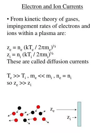
Experiments Over-linear sub-linear Conductance* • measured in voltage-clamp experiments • Asymmetric I-V characteristic: over linear increase in the first quadrant and sub linear in the third. • Linear relationship between the channel conductance and the conductivity (molarity) of the electrolyte solution at a constant clamp voltage. • The channel is slightly anion- selective at pH 7.0 * Biophysical Journal, 79, 4, 1967-1975, 2001
Alpha hemolysin channel in 1.0 M KCl solution with an external applied voltage of 125 mV leads to an ionic current of 120 pA (channel conductance ~1nS) ss-DNA or RNA molecules driven by an electric field through the ion channel generate a transient decrease of ionic current CIS TRANS - + ELECTRIC FIELD A bio-engineering application
Left handed a-helix b-sheet Right handed a-helix Atomistic model • pdb file from the protein data bank: http://www.rcsb.org/pdb/ • Structure resolved via X-ray diffraction ~1.6 Å at 287K and a pH of 6* • Ramachandran plot: backbone phi, F – psi, Y angles (-180 to 180 deg) • Topology file generated in Amber using the parm94 force field** *Song, L., Hobaugh, M. R., Shustak, C., Cheley, S., Bayley, H., Gouaux, J. E., Structure of staphylococcal alpha-hemolysin, a heptameric transmembrane pore, Science 274 pp. 1859 (1996) **Force field: Cornell et al, 1995 –AMBER, http://www.scripps.edu/
C1 Geometry C1:GLU(111) z=-11Å, R=7.4 Å acid turn LYS(147) z=-11Å, R=6.1 Å basic MET(113) z=-19Å, R=6.4 Å hydrophobic turn THR(145) z=-19Å, R=8.2 Å hydrophilic C2:LEU(135) z=-47Å, R=6.3 Å hydrophobic C2 C1
ELECTRONS ATOMS GRAINS GRIDS time hours seconds nanosec picosec femtosec Continuum (macroscopic equations, PNP) MESO MD QM Å nm micron mm cm meters distance Multi-scale modeling* * Goddard group, http://wag.caltech.edu/
Diffusion coefficients Dp,Dn of the ions • Fixed pore charges rf Molecular Dynamics Poisson V(z,r,0) Cn(z,r,t) Cp(z,r,t) V(z,r,t) Nerst-Plank Open Channel Ion Current • At steady state, the current gradients are zero MD-PNP hybrid model
Benchmarking for NAMD http://www.ks.uiuc.edu/Research/namd/ • Solvated protein: 175,364 atoms, cutoff 20Å, UC~130Å, Dt=2fs: 3.52days/ns 128 CPU • Benchmark system: 92,000 atoms, cutoff 12Å, UC~109Å, Dt= 1fs: 1.61days/ns 128 CPU Actual system: 120,000 atoms, cutoff 20Å, Dt=2fs (MTS): 1.29 days/ns for 200 CPU
SPC/E water model • SPC/E model: q(O)=-0.8476e, q(H)=0.4238e
Ionic solution, 1MKCl • crystal structure arrangement of atoms (NaCl) • selected number to correspond to 1M solution (1KCl pair for ~55 water molecules) • box with 400 KCl pairs K+ Van der Waals parameters (Aquist): R* = 2.658Å; e= 0.000328 DG = -80.9kcal/mol; Cl- Van der Waals parameters (Smith&Dang): R* = 2.47Å; e=0.01; D(mutual) = 2.9*10-9m2/s D( dilution) = 1.8*10-9m2/s
MD procedure • minimization for 5000 steps • heating to 300K in steps of 50K • NPT equilibration of solution for 400ps (time step 2fs) • dynamics for ~1ns using MTS-NVE • Pure diffusion • External applied electric field
KCl solution inside the pore V=125 mV; Lz = 100 Å; 1 e-=1.6·10-19 C; 1Å = 10-10 m; E = 0.0288 kcal/mol/Å /e-;
- + ELECTRIC FIELD 1K at z = 60Å (center) DIFFUSION EEL ~ 40 kcal/mol VdW ~ -0.03 kcal/mol EEL~ 15 kcal/mol; VdW ~ -0.02 kcal/mol EEL ~ -2 kcal/mol VdW ~ -0.01 kcal/mol
Pore volume CONNOLY CALCULATIONS PORE: Rp=1Å V1 = 97199.9 ± 1186.3 Å3 Rp =1.4Å V1.4 = 98508.6 ± 738.7 Å3 Rp =25Å V25 = 212437.4 ± 2466.8 Å3 Vpore= 114583 ± 2835 Å3 n~69 ions 1M = N moles solute/1L solution =NA molecules/1027Å3 =6.023E-4 molec/Å3
water –15<E<-2.5 kcal/mol Cl –9<E<-2.5 kcal/mol K –40<E<-12 kcal/mol K –40<E<-6 kcal/mol Cl –9<E<-1.5 kcal/mol water –15<E<-5 kcal/mol Binding energies in the pore
r z 2-D Poisson Nerst Plank (PNP) Schematic representation of a-hemolysin channel. In the PNP model a 2D grid (represented as concentric rings) corresponding to a cylindrical polar coordinate system (radial and axial) is applied over the pore stem.
e=80 e=20 e=80 0.120 (V) e=80 e=20 e=80 + 0 VOLTAGE Electrostatic potential maps Pore constrictions and transmembrane voltage (no fixed charges) Pore constrictions, transmembrane voltage and fixed charges
Channel selectivity Anion selective Experimental values: 1M KCl, 120mV G~1nS; 0.5M t(K+)/t(Cl-) ~ 1.5 * Menestrina, G, The Journal of Membrane Biology, 90, 177-190, 1986
Open Channel Ion Current MD-PNP calculations * Menestrina, G, The Journal of Membrane Biology, 90, 177-190, 1986
The MD calculations show that both K+ and Cl- ions are transported through the a-hemolysin channel The ions diffusion coefficient inside the pore is reduced by a factor of ~5 for K+ and ~6 for Cl- compared to pure solution. Overall (in solution and in the pore) D(K+) > D(Cl-) while in the pore-cap D(K+) < D(Cl-) Binding sites for K+ occur at the two ends of the pore (cis and trans) while for Cl- the best binding sites are located at the stem-cap connecting region There is a greater binding potential and also more binding sites for K+ than Cl- 2D-PNP model prediction show that I-V behavior is consistent with observed experimental profiles: over-linear for positive voltages and sub-linear for negative voltages A smooth cylinder would have a larger conductance that is reduced by the presence of the two constrictions The polar walls of the pore increase the current Channel is slightly anion (Cl-) selective CONCLUSIONS
MD simulations with NAMD(http://www.ks.uiuc.edu/Research/namd*) Movies and analysis generated with VMD(http://www.ks.uiuc.edu/Research/vmd*) Amber, VMD, NAMD lists, GRID (Molecular Inc) NAS support group (http://www.nas.nasa.gov) System administrators of the Nanotechnology Division: Aldo Foot, Marcy Shull ACKNOWLEDGEMENTS *VMD/NAMD - developed by the Theoretical and Computational Biophysics Group in the Beckman Institute for Advanced Science and Technology at the University of Illinois at Urbana-Champaign.
The temperature factor(B- or Debye-Waller factor) B(eq) = 8pi**2{1/3[U(1,1) + U(2,2) + U(3,3)]} • the molecular motions in the simulation (thermal vibrations) can be related to crystallographic Bi factors (calculated from X-ray scattering) • Bi is the temperature factor of atom i • Ui is the mean square displacement of atom i • The pore stem and the pore inside are the “dynamically active” parts
Hydrophobicity map • Alternating layers with high (blue) and respectively low (red) hydrophobicity • Hydrophobicity influences the ongoing dynamics: hydrophylic residues will form more HB with water thus the local friction coefficient will be larger
- + ELECTRIC FIELD ‘Ingredients’ for the MD modeling The a-hemolysin pore 1M KCl Force field: Cornell et al, 1995 –AMBER, http://www.scripps.edu/ Multi-CPU scalable MD software: NAMD*, http://www.ks.uiuc.edu/
- + ELECTRIC FIELD DIFFUSION 1K at z=35Å (trans) Interaction energy K+-protein Electrostatic ~ 15 kcal/mol VdWaals ~ -0.02 kcal/mol
- + ELECTRIC FIELD 1K at z=90Å (cis) DIFFUSION Interaction energy K+-protein Electrostatic ~ -2 kcal/mol VdWaals ~ -0.01 kcal/mol
- + ELECTRIC FIELD 1K along channel axis Diffusion