Download
1 / 29
290 likes | 428 Vues
R&D status report on LST technology. Changguo Lu Princeton University BaBar IFR Workshop SLAC, November 14-15, 2002. Outlines. Selection of the safe gas mixture for the LST system; Performance of the new double-layer prototype; Preliminary aging test result for a PVC LST chamber;

E N D
R&D status report on LST technology Changguo Lu Princeton University BaBar IFR Workshop SLAC, November 14-15, 2002
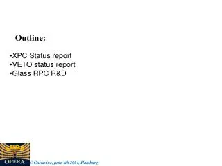
Outlines • Selection of the safe gas mixture for the LST system; • Performance of the new double-layer prototype; • Preliminary aging test result for a PVC LST chamber; • R&D plan for the next.
Why this gas mixture is safe? The Isobutane/CO2 (10/90) line won’t cross the edge of the flammable region of Isobutane/CO2, therefore this is a non-flammable gas mixture. If we use even less isobutane this line will further away from the contour. According to this plot, BaBar DCH gas mixture (He/C4H10(80/20)) is a flammable gas, so it needs to take extreme precaution to use this gas mixture. Flammable gas mixture of CO2/C4H10/Air C4H10/CO2 (10/90) line (David Strom, Gas used in RPC test, 8/3/2001, Based on Bulletin 627, U.S. Bureau of Mines, 1965, Zabetakis, M. G.)
Pulse size to charge conversion constant CV-Q = 0.38pC/mV 30mV 11pC The QDC used in our test has sensitivity = 0.125pC/channel, the overall pulse size to channel conversion constant = 3ch/mV.
Drift time in this gas mixture Use CERN Garfield and Magboltz programs we can predict the drift time in a LST cell with certain precision.
Gas gain in this gas mixture Use CERN pcmonte program can estimate the gas gain, then predict the transition point to the limited streamer mode.
Efficiency test Trigger system used for this test
… Efficiency Because our trigger counters are made of LST chambers, in some areas the electron drift time can be longer than 100ns. Delay cables used are 100ns long. Sometimes the trigger signal is lagging behind the test chamber signal, therefore the recorded is only a partial signal, that causes many events are located at small signal region. That pulls down the measured efficiency. Right size of scintillation counters are under construction. We are expecting the efficiency will be slightly better than reported. That will compensate the loss due to the dead space between 8-cell chambers. The overall efficiency will be maintained at the same level as we reported here: 96%.
Aging test setup X-ray irradiation distribution along anode wire direction
… Aging test setup To speed up aging test we use Sr-90 source (~0.2mCi) instead. Use aging test LST chamber with strip readout to determine particle profile.
Particle intensity profile Source shutter open, 59% of total rate is on wire #5, therefore 1x1cm2 area direct under the collimator hole would get 35% of total rate. Source shutter close, the rate is unformly distributed among all 8 wires, which indicates the cosmic ray distribution.
Aging test parameters • Gas mixture: Ar/C4H10/CO2(3/8/89), ZEUS gas mixture; • HV: 4700V; • PVC chamber, geometry: 9 x 9 mm2 cell size, 100µm anode wire (same as SMC PST chamber, SCARF made); • Gas flow rate: 28 sccm for 5 1.5m-long 8-cell chambers. • Monitor charge spectrum and signal’s rate for: • Cosmic ray background, • Fe-55 source on aging test window, • Fe-55 source on control window; • Record current drawn by anode wire all the time; • Record room temperature and atmospheric pressure.
Temperature effect on the current Clearly see this current drop is due to temperature effect.
More aging test results: ratios The ratio between the aging window and control window also shows no sign of aging. Temperature drop doesn’t affect the ratio. The big fluctuation of the ratio of counting rate could be due to pickup noise effect, but has not completely studied yet.
… more aging test results and rate capability Charge spectra from aging window, reference window and cosmic background are coincided with each other, no aging sign. The spectrum of aging window is generated by Fe-55 source, the rate is ~75Hz/cm2, there is no difference from cosmic ray background – rate capability of PST is certainly higher than 75Hz/cm2.
Conclusion from aging test • In a PVC LST chamber we have conducted an aging test with gas mixture of Ar/C4H10/CO2 (3/8/89), up to 93mC/cm there is no aging symptom shown up yet. For BaBar barrel IFR upgrade aging won’t be an issue for LST technology. • CHARM II aging test results: w/o adding additional water vapor into the gas mix, the aging showed up after ~10mC/cm. With 4000ppm water vapor, no aging up to 110mC/cm. The gas mix was Ar/Isobutane (1/2.4). Our system is not water-free: Polyflo tubing is water permeable, the PVC envelop can permeate water vapor either. 5000ppm water!! Wit Busza, NIM A265(1988)210
… Conclusion from aging test • Comparison to SMC’s experience: • SMC claimed at the level of 5~10 C/cm, there was 50% of failure rate, and at a few C/cm level, 10% of failure rate. For BaBar barrel IFR the expecting charge dose of layer #1 is ~0.05 C/cm up to 2010 (J. Va’vra’s estimation, assuming 100pC/track) << SMC’s failure dose. • Jerry suggested 100~200 mC/cm aging test, we almost reached 100 mC/cm mark, we’ll investigate 200 mC/cm dose limit. • According to Jerry’s estimation the endcap layer 18 should expect 2C/cm for PST chambers.
R&D plan for the next step • Assembly site QA procedure study; • Further aging study; • Search for even better gas mixture: safe, better aging, wider plateau; • Strip plane study: Z strip readout; • …
… R&D: QA Assembly site QA procedure I will leave this topic to Mario. For the technology such as LST, it is robust, easy to operate, but also has the tendency to cover up the defect at the very beginning of its life. One of the most difficult task is how to find the bad and potentially bad chambers after the mass production – effective QA procedure. Before we adopt a procedure we have to test it, and understand the power and limit of this procedure.
… R&D: Aging Aging test results vary from group to group, important thing is using chambers built with exactly same material as the real chamber and same gas mixture to do the test. We will start a new aging test with a Noryl chamber and to see if this technology is good for endcap layer 17, 18 as well (2C/cm2 limit).
… R&D: Gas mixture • Add water vapor? How much? • Add small amount of SF6 to reduce streamer signal size for better aging and possibly wider plateau; • How to further suppress after pulse with the safe gas mixture; • Any suggestion is welcome.
… R&D: Strip plane • In a very tight gap space to get the Z-strip signal out is a challenging task. • We have to address the issues such as: • efficiently transmit the induced signal from the middle of the chamber to two ends; • avoid cross talk between neighboring traces; • use minimum space to accomplish the task. • In Livio’s talk he’ll talk this further more.
… R&D: Full length prototype We’ll test full length prototype (3.7m long) in near future.
Conclusion on R&D • Based on the past experiences from various LST systems worldwide and our own R&D on the single-layer and double-layer configuration we have proved the feasibility of LST technology for BaBar barrel IFR upgrade; • The aging test shows rather encouraging result, even for PVC LST chamber would survive the charge dose for the inner layer of barrel IFR up to 2010, further aging test will be for Noryl PST chamber and see if LST is good for endcap layers 17, 18 as well; • We’ll establish a reliable QA procedure for accepting LST chambers before putting them into the final assemblies; • We already have our baseline safe gas mixture (Zeus/SLD LST gas), more detailed R&D on the gas mix is aimed to get better understand of the gas and decide whether or not to add water vapor or other additive.