Download
1 / 20
200 likes | 277 Vues
There were 32 excellent talks. I will not go through them one by one, but rather try to capture the flavour. (If I say nothing about your talk, I apologize; it is not a reflection of its quality.) .

E N D
There were 32 excellent talks. I will not go through them one by one, but rather try to capture the flavour. (If I say nothing about your talk, I apologize; it is not a reflection of its quality.) Summary of Group A: Beam Dynamics in High-Intensity circular machines--Giuliano Franchetti, Elias Metral, Rick Baartman (reporter)
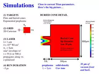
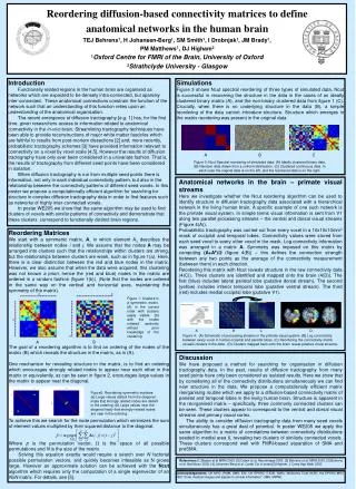
a. Simulations Andreas Adelmann gave a talk in which he pointed out that parallelization of tracking codes has so far not yielded spectacular gains. The reason is that there has been a concentration on the physics aspects without a concommitant parallelization of the other aspects. AA also reported on the remarkable gains made in compute efficiency when going to an appropriate Lorentz-boosted reference frame. Both of these aspects are areas of future developments for improving code speed.
a. Simulations, cont'd Ecloud (Furman): electron cloud is observed in the FNAL Main Injector, but it is not an operational limitation. Furman made simulation studies for higher intensities (for neutrino program), which revealed to be almost insensitive to the beam energy. This is in qualitative disagreement with measurements (also SPS observations reported by Arduini at ECLOUD04). ORBIT code painting simulations for ISIS (Warsop) seemed to agree well with measured profiles. However, as I understand, there is no deep physical understanding of how to paint to minimize losses.
a. Simulations, cont'd We had a protracted discussion on simulation codes and their uses/abuses. There is a general understanding that simulations are important not only for the design, but also for optimizing the machine. An example is brought by V.Lebedev, who reports that 7 years of optimization were needed to bring the Tevatron to its current luminosity. Each optimization is obtained in steps where the machine performances are increased via consistent studies and simulations. The need to establish a set of standard benchmarking/validating simulations has been proposed, but not discussed in detail. A difficulty is that benchmarking for the international community is often not seen as a lab priority. It was therefore proposed that Rob Ryne ask for funding from SCIDAC for this purpose. :-) Another proposal arising from the discussion is to convert the existing but obsolete Code compendium/webpage to a wiki and leave it up to the authors to keep the description and “CV” up to date. That way, someone with a particular kind of problem can more easily find the best code to simulate it.
a/b. simulation/theory Ingo Hofmann gave an interesting paper regarding a way to summarize the effect of crossing a resonance. Define the parameter S= (Qx2) / d(Qx0) / dn In simulations, it is found that emittance growth on crossing various resonances can be found by taking S to some power; the higher the order of the resonance, the higher the power. This scaling law is very useful for quick evaluation of dangerous regimes. Later, after we had discussing bunched beams and also the FNAL Booster, Ingo realized that the betatron tune changing because of synchrotron motion is also captured by this scaling factor, since then d(Qx0) / dn ~ Qx0 Qs, and S~ Qx / Qs , which counts the number of synchrotron sidebands inside the tune shift. Thus in both cases, S can be understood as a kind of adiabaticity parameter: if it is large, it means the beam will act like a coasting beam, and the picture of particles in frequency space crossing betatron lines is the correct one. If it is small, this picture is not correct. The benchmarked Montague resonance never quite agreed experimentally with the codes. This might be due to insufficiently slow synchrotron motion.
b. Summarize the state of the art in theory. What developments are needed? Resistive-wall impedance (F. Roncarolo): Numerical simulations and laboratory measurements have been performed for the first time (to our knowledge) in the low-frequency regime of interest for the transverse resistive-wall impedance of a LHC graphite collimator (between ~ 10 kHz). The agreement with new theories published in the last years (Henry-Napoly, Burov-Lebedev, Zotter, and Al-Khateeb et al.) is impressive.
b. theory – cont'd TMCI (B. Salvant) For several years now, a fast vertical instability is being studied at SPS injection with an LHC-type bunch of low longitudinal intensity (in view of future intensity upgrades). It is becoming more and more clear that this is a TMCI. A double instability threshold (Stable-unstable-stable again-unstable again as intensity increased), and a tune step were observed on both simulations of the 20 kickers impedance and on SPS experiments performed in 2007. These two typical features of TMC instabilities are yet again other indications that the fast instability observed in the SPS could be explained by a coupling between modes “-2” and “-3”. Furthermore, it is worth mentioning that simulation studies were performed with a flat chamber compared to a round one, and without and with space charge. In both cases the effect is rather small (~ 20 %) which is believed to be understood by the fact that the mode coupling does not occur between modes 0 and -1 (as usual in electron machines) but between higher order modes. Note also that it was checked with HEADTAIL simulation that in the case of a flat chamber, linear coupling can raise the intensity threshold by ~30% as foreseen in some theories.
b. theory – cont'd gamma-t: to cross or not to cross: In the CERN PS, the nTOF has to be blown up longitudinally before crossing transition otherwise all the bunch is lost due to a fast vertical instability. V. Ptitsyn told us that at RHIC, a transverse instability presently limits the ion beam intensity. The current explanation of these effects is that the electron cloud, accumulated in the beam with large number of bunches, lowers the instability threshold and introduce the dependence of instability strength on bunch train position. Elena Shaposhnikova raised the following question: For future machines, should we cross transition or not, if this can be avoided using a lattice with a negative imaginary gammaT. Experts at our discussion unanimously said NO, one should try and avoid it. Even though many tricks have been developed over the years there are always some losses near transition.
b. theory – cont'd Space charge effect on Landau damping V. Kornilov, V. Lebedev and B. Ng talked about this subject and previous work by D. Mohl, Metral-Ruggiero. It seems that there is a relatively good agreement for coasting beams. For bunched beams, the situation is much more involved and some work is still needed to get a good understanding of the effect of space charge and longitudinal nonlinearities on Landau damping. (It would have been nice if Mike Blaskiewicz was here...) O. Boine-Frankenheim showed interesting results for simulated transverse Schottky signals which could help understanding the effect of space charge on head-tail modes. These were interesting for two reasons...
b. theory – cont'd The instability in the FNAL Booster, mentioned in a talk in HB2006 as an unsolved mystery, has been solved. Burov and Lebedev presented a convincing case that it is the third synchrotron sideband of the integer. Qx,coh=6.85=n-3Qs, since Qs=0.05. The driving force is dispersion at the rf gaps. A confusing aspect is that the clearest signature appears in the vertical instead of the horizontal plane. This is due to the strong coupling and unsplit tunes. Currently, instability is minimized by going to very high chromaticity. This does not solve it; it simply makes it somewhat weaker. A better solution would be to arrange the cavities in a symmetric pattern so the driving kicks are cancelled. The theory was developed, including the effect of chromaticity.
b. theory – cont'd Edouard Pozdeyev gave an interesting talk on a kind of beam breakup effect that occurs in isochronous rings. This effect will cause a long bunch to break into droplets, since the stationary distribution is a circular cylinder. The final bunches have the same length as their original width. This may have consequences for rings that stay a long time near transition. It is also observed in the PSI cyclotron, and hints of it have been seen in the TRIUMF cyclotron.
a. simulation – (out of sequence) In the case of the PSI, this effect could be related to the talk by Andreas Adelmann (standing in for Jianjun Wang) where he described simulations of their ring cyclotron: the incoming beam is prepared so that there is only one of these "droplets", and so magically, even though space charge force is not small, it serves to help, not hinder the maintenance of very short bunches. That was not, however, the main point of the talk (since this effect is "old hat" to cyclotron people), rather, the new result is that they can now simulate the effect of side-by-side bunches on each other. It appears that the effect is to sharpen the bunches further, making for better turn separation. This is a surprise and the new simulation is a major advance in the cyclotron (/FFAG) field.
c. Summarize recent developments in benchmarking experimental data with simulations. What critical experiments and diagnostic developments are needed to further refine the theory and simulations? Measurements have been performed in the CERN PSB (M. Martini) to try and understand the space charge mechanisms in view of the future operation with LINAC4 (at 160 MeV, replacing the LINAC2 at 50 MeV). These measurements have been benchmarked against ACCSIM and ORBIT. The agreement is rather good between measurements and ORBIT. However there are significant discrepancies between ACCSIM and ORBIT (which were not present in the benchmarking of the Montague resonance in the PS) which still need to be understood.
c. benchmarking Resistive-wall instability is damped on the long injection flat-bottom of the CERN PS by linear coupling. HEADTAIL simulations recently confirmed that linear coupling can be used to damp a transverse coherent instability, as observed and theoretically predicted in the past. This method is used since ~ 10 years! V. Lebedev and A. Burov published a new theory on the effect of coupling on the beam dynamics, and these results should be compared to the previous ones and PS observations. This is a candidate for benchmarking the RW effect.
e. Summarize the primary limitations to beam intensity in existing circular machines. Aside: The luminosity goal of LHC was set long ago. Seemed reachable, but then we became worried of E-Cloud, then later we solved this. Now the limitation lies elsewhere. The point is that intensity limitations can always be overcome if we work at it. PS-booster space charge/ betatron stopbands; Fermilab booster synchro-betatron resonances and probably space charge and the 13/2 resonance PS large space charge creates problems. the beam intensity limitation is the transition (gamma jump) TMCI Cured with longitudinal blow-up (it is a brightness limitation!). SIS18 limited by space charge and lattice nonlinear resonances; SPS EC build-up. The instability are cured via chromaticity; existence TCMI. It will become a problem for an increased brightness . ISIS space charge & betatron resonance; RHIC transverse instability at transition due to EC;
crossing space charge resonances I. Hofmann
space charge and resonances in high intensity beams space charge nonlinearity can itself be a source of resonance in LINAC and RING forces considered: “octupolar” and “decapolar” 4th order resonance (Montague) 6th order resonance transverse/longitudinal emittance exchange 2kz - 2kx ~ 0 4th order x/y emittance exchange 2Qx – 2Qy ~ 0 when crossing the resonance beam emittances exchange totally or partially according to the speed of crossing.
space charge and resonances in high intensity beams space charge nonlinearity can itself be a source of resonance in LINAC and RING forces considered: “octupolar” and “decapolar” 4th order resonance (Montague) 6th order resonance transverse/longitudinal emittance exchange 2kz - 2kx ~ 0 4th order x/y emittance exchange 2Qx – 2Qy ~ 0 when crossing the resonance beam emittances exchange totally or partially according to the speed of crossing.
space charge and resonances in high intensity beams space charge nonlinearity can itself be a source of resonance in LINAC and RING forces considered: “octupolar” and “decapolar” 4th order resonance (Montague) 6th order resonance transverse/longitudinal emittance exchange 2kz - 2kx ~ 0 4th order x/y emittance exchange 2Qx – 2Qy ~ 0 when crossing the resonance beam emittances exchange totally or partially according to the speed of crossing.