Download
1 / 22
430 likes | 1.11k Vues
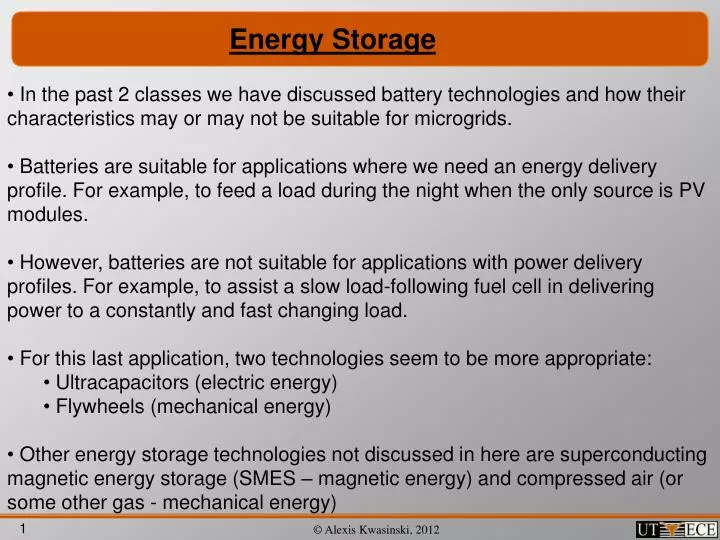
Energy Storage. In the past 2 classes we have discussed battery technologies and how their characteristics may or may not be suitable for microgrids.

E N D
Energy Storage • In the past 2 classes we have discussed battery technologies and how their characteristics may or may not be suitable for microgrids. • Batteries are suitable for applications where we need an energy delivery profile. For example, to feed a load during the night when the only source is PV modules. • However, batteries are not suitable for applications with power delivery profiles. For example, to assist a slow load-following fuel cell in delivering power to a constantly and fast changing load. • For this last application, two technologies seem to be more appropriate: • Ultracapacitors (electric energy) • Flywheels (mechanical energy) • Other energy storage technologies not discussed in here are superconducting magnetic energy storage (SMES – magnetic energy) and compressed air (or some other gas - mechanical energy)
Power vs. energy delivery profile technologies • Ragone chart: • More information and charts can be found in Holm et. al., “A Comparison of Energy Storage Technologies as Energy Buffer in Renewable Energy Sources with respect to Power Capability.”
Electric vs. Magnetic energy storage • Consider that we compare technologies based on energy density (J/m3) • Plot of energy density vs. length scale (distance between plates or air gap): • Hence, magnetic energy storage (e.g. SMES) is effective for large scale systems (higher power) University of Illinois at Urbana-Champaign ECE 468 (Spring 2004)
Ultracapacitors • Capacitors store energy in its electric field. • In ideal capacitors, the magnitude that relates the charge generating the electric field and the voltage difference between two opposing metallic plates with an area A and at a distance d, is the capacitance: • In ideal capacitors: • Equivalent model of real standard capacitors:
Ultracapacitors • Ultracapacitors technology: construction • Double-layer technology • Electrodes: Activated carbon (carbon cloth, carbon black, aerogel carbon, particulate from SiC, particulate from TiC) • Electrolyte: KOH, organic solutions, sulfuric acid. http://www.ultracapacitors.org/img2/ultracapacitor-image.jpg
Ultracapacitors • Ultracapacitors technology: construction • Key principle: area is increased and distance is • decreased • There are some similarities with batteries but there are • no reactions here. Ultracapacitor with carbon nano-tubes electrodes Double layer capacitor (ultracapacitor) Traditional standard capacitor The charge of ultracapacitors, IEEE Spectrum Nov. 2007
Ultracapacitors • Ultracapacitors technology: construction www.ansoft.com/firstpass/pdf/CarbonCarbon_Ultracapacitor_Equivalent_Circuit_Model.pdf
Ultracapacitors • Some typical Maxwell’s ultracapacitor packages: • At 2.7 V, a BCAP2000 capacitor can store more than 7000 J in the volume of a soda can. • In comparison a 1.5 mF, 500 V electrolytic capacitor can store less than 200 J in the same volume. www.ansoft.com/firstpass/pdf/CarbonCarbon_Ultracapacitor_Equivalent_Circuit_Model.pdf
Ultracapacitors • Comparison with other capacitor technologies www.ansoft.com/firstpass/pdf/CarbonCarbon_Ultracapacitor_Equivalent_Circuit_Model.pdf
Ultracapacitors • Charge and discharge: • With constant current, voltage approximate a linear variation due to a very large time constant: • Temperature affects the output (discharge on a constant power load): www.ansoft.com/firstpass/pdf/CarbonCarbon_Ultracapacitor_Equivalent_Circuit_Model.pdf
Ultracapacitors • Aging process: • Life not limited by cycles but by aging • Aging influenced by temperature and cell voltage • Overtime the materials degrade, specially the electrolyte • Impurities reduce a cell’s life. Linzen, et al., “Analysis and Evaluation of Charge-Balancing Circuits on Performance, Reliability, and Lifetime of Supercapacitor Systems”
Ultracapacitors • Power electronic interface: • It is not required but it is recommended • It has 2 purposes: • Keep the output voltage constant as the capacitor discharges (a simple boost converter can be used) • Equalize cell voltages (circuit examples are shown next)
Ultracapacitors • Model (sometimes similar to batteries) Mierlo et al., Journal of Power Sources 128 (2004) 76–89 http://www.ansoft.com/leadinginsight/pdf/High%20Performance%20Electromechanical%20Design/Ultracapacitor%20Distributed%20Model%20Equivalent%20Circuit%20For%20Power%20Electronic%20Circuit%20Simulation.pdf Ultracapacitors for Use in Power Quality and Distributed Resource Applications, P. P. Barker
Flywheels • Energy is stored mechanically (in a rotating disc) Motor Generator Flywheels Energy Systems
Flywheels http://www.vyconenergy.com http://www.pentadyne.com
Flywheels • Kinetic energy: • where I is the moment of inertia and ω is the angular velocity of a rotating disc. • For a cylinder the moment of inertia is • So the energy is increased if ω increases or if I increases. • I can be increased by locating as much mass on the outside of the disc as possible. • But as the speed increases and more mass is located outside of the disc, mechanical limitations are more important.
Flywheels • Disc shape and material: the maximum energy density per mass and the maximum tensile stress are related by: • Typically, tensile stress has 2 components: radial stress and hoop stress.
Flywheels • Since • (1) • and • (2) • and • (3) • then, from (2) and (3) • (4) • So, replacing (1) in (4) it yields
Flywheels • However, high speed is not the only mechanical constraint • If instead of holding output voltage constant, output power is held constant, then the torque needs to increase (because P = Tω) as the speed decreases. Hence, there is also a minimum speed at which no more power can be extracted • If • and if an useful energy (Eu) proportional to the difference between the disk energy at its maximum and minimum allowed speed is compared with the maximum allowed energy (Emax) then Eu/Emax Bernard et al., Flywheel Energy Storage Systems In Hybrid And Distributed Electricity Generation Vr Vr
Flywheels • In order to reduce the friction (hence, losses) the disc is usually in a vacuum chamber and uses magnetic bearings. • Motor / generators are typically permanent magnet machines. There are 2 types: axial flux and radial flux. AFPM can usually provide higher power and are easier to cool. Bernard et al., Flywheel Energy Storage Systems In Hybrid And Distributed Electricity Generation Bernard et al., Flywheel Energy Storage Systems In Hybrid And Distributed Electricity Generation
Flywheels • Simplified dynamic model • Typical outputs Flywheels Energy Systems