Download
1 / 19

E N D
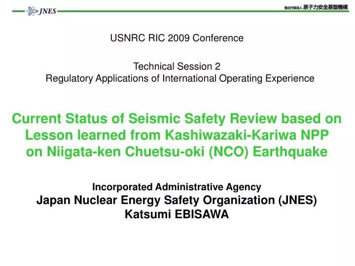
USNRC RIC 2009 ConferenceTechnical Session 2Regulatory Applications of International Operating ExperienceCurrent Status of Seismic Safety Review based on Lesson learned from Kashiwazaki-Kariwa NPP on Niigata-ken Chuetsu-oki (NCO) EarthquakeIncorporated Administrative Agency Japan Nuclear Energy Safety Organization (JNES)Katsumi EBISAWA
A. Nuclear Safety Regulation in Japan NSCJ Nuclear Safety Commission of Japan Established in 1978, Staff: ~100 ・Safety review ・Regulatory guides METI, NISA Nuclear and Industrial Safety Agency Established in 2001, Staff: ~800 ・Safety review ・Licensing, etc. Licensees Apply for permit Report Safety review Oversight Instruction of review Report of cross check analysis JNES Japan Nuclear Energy Safety Organization Established in 2003 Staff: ~460 ・Support of review, inspection ・Safety Research, etc. Do Cross check analysis: Review the utility report technically as TSO of NISA Establish Seismic Safety Division in Oct.2007, after NCO EQ 1
B. Progress in Seismic Safety Regulation in Japan Northridge EQ Kobe EQ NCO EQ NRC meet. (2006~2010) (~2000) (2001~2005) (2011~ ) Kobe EQ (1995.1) Northridge EQ(1994.12) NCOEQ (2007.7) 2006.9 2001.7 2006.9 2007.7 2006.9 2007.7 IAEA Seismic Safety Center (2008.10) IAEA-JNES Tsunami EBP (2007~2009) Information exch.with NRC(2008.7) 2
Ⅰ.Activities after Revision of Seismic design Guide ■NSCJ ・Main features of revised seismic design review guide ■Atomic Energy Society of Japan (AESJ) ・Established Seismic PSA Implementation Standard based on consideration of residual risk in the new seismic design review guide (2007.9) ■NISA ・Required the licensees to re-evaluate seismic safety of existing NPPs according to the new seismic design review guide (2006.9) ⇒ Re-evaluation: 1st step- deterministic approach, 2st step- Residual risk 3
Ⅱ.Status of Seismic Re-evaluation ■Review by NISA ・Organize Subcommittee related to seismic safety re-evaluation NCO EQ (2007.7) Interim report Utility Final report Review of interim report Review of final report ■NISA’s direction to reflect recent findings and lessons learned from NCO earthquake (2007.7) ・To TEPCO: to investigate causes and to confirm plant integrity (2007.7) ・To JNES: to carry out cause analysis and cross-check to TEPCO’s result (2007.10) ・To licensees: to reflect cause analysis result by JNES to seismic safety re-evaluation (2008.9) 4
Ⅲ.Process to deal with NCO EQ by NISA 1/2 1. Cause analysis of earthquake 2. Integrity evaluation to NCO EQ Earthquake and ground motion characteristics Building response characteristics Evaluate elastic limit (urgently)(Criteria ⅢAs) Inspection Analysis ・Building / facility integrity Observed G.M. Additional inspection ・Building / facility Integrity 3. Re-evaluation (Criteria ⅣAs) Facility with small margin Standard ground motion Ss ・Reinforcement (voluntary) ・Building and facility integrity 5
Process to deal with NCO EQ by NISA 2/2 1.Cause analysis of earthquake 2. Integrity evaluation to NCO EQ Earthquake and ground motion characteristics Building response characteristics Evaluate elastic limit (urgently)(Criteria ⅢAs) ・Floor flexibility ・Building-soil interaction Inspection ・Source charac- teristics ・Deep under- ground structure Analysis ・Building / facility integrity Observed G.M. JNES cross-check analysis ⇒Causesresolved and approved by Subcommittee Additional inspection ・Building / facility Integrity 3.Re-evaluation (Criteria ⅣAs) Facility with small margin Standard ground motion Ss JNES cross-check analysis of Units 6&7 ⇒Evaluation result approved by Subcommittee ・Reinforcement (voluntary) ・Building and facility integrity JNES cross-check analysis of Unit 7 ⇒ Evaluation result approved by Subcommittee 6
1.Cause Investigation on NCO EQ ■ Characteristics of Earthquake Main shock: ・July 16, 2007 ・Mj : 6.8 ・Depth : 10 km ・Epicenter Distance: 14 km ■ Earthquake Motion observation at Reactor Building Epicenter Kashiwazaki Site Ground Surface ■ Location of Units K1-7 North Service Hall 3rd floor 2nd floor K5 K6 K7 1st floor 1st basement Soil Dump 5th basement Seismometer on the Building Foundation K4 K3 K2 K1 About 2.5 km Vertical Array observation South Japan Sea 7 8
(1)Features of Observed Waves and Response Spectra on Reactor Building Unit 5 Unit 1 Unit 2 Unit 3 Unit 4 Unit 7 Unit 6 Acceleration (Gal) Generation of 3 Pulse Waves Response Spectra of Unit 4 Building Response Spectra of Unit 1 and 5 Design Unit 1 Unit 5 Observed Observed Acceleration (Gal) Acceleration (Gal) 680 Gal Observed Design Design Period (s) 273 Gal Period (s) Period (s) Contents of Cause Investigation Ⅰ.Amplification Characteristics of the Sources and the Seismic Ground Motions (1) Why did 3 pulses happen ? (2) Why did the observed seismic ground motions exceed those designed and the Unit 1 shows the highest values which are nearly double of the design response ? (3) Why did the acceleration values of observed seismic motions of the Unit 1 become nearly double of the Unit 5 ?(Those two Units locate in 2.5 km apart each other in the site). Ⅱ.Response Spectral Characteristics of Buildings (1)Why were the response spectra derived from the observed seismic motionsdifferent from those of the vibration model of the conventional seismic design ? 8 9
(2) Analysis of Effectsof Sources and Seismic Ground Motions Analysis of the effects of source characteristics Asperity 1 (Rupture starting: 0 sec) ★: Rupture starting point Asperity 2 (Rupture starting: 3 sec) NPP Asperity 3 (Rupture starting: 7.8 sec) Observed wave form NPP Plane section Cross section Asperity 3 (EW): Strong radiation • Sequential rupture of 3 asperities which broke out strong seismic motion is • one of causes of amplifying pulse wave. • (ii) Asperity 3 is very close to the site, and radiates strong seismic motion. 9
Perspective View Direction Japan-Sea Side ← N W Epicenter Anticline E The Site → Kanto Side (3) Analysis of Effects of Deep Ground Structure Generation of 3-D Underground Structure Model Used data: Boring surveys, reflection surveys, geological maps, etc., performed by the former Japan National Oil Corporation. Kanto Side ← → Japan-Sea Side The Site W E Ground Surface Nishiyama Shiiya Upper Teradomari Lower Teradomari Free Base Stratum Depth = 150 – 250 m Green Tuff / Nanatani Bedrock Source Area Seismic Base Stratum Depth = 5000 – 8000 m (Vs:km/s) • Earthquake bedrock near the site is deep as about 5~8 km. • (ii) The deep underground structure has irregularity in propagation path of seismic motion from epicenter. 10
敷地 解放基盤 敷地に直達する 地震動の伝播経路 地震基盤 Analysis of Amplification Characteristics of Pulse Waves at Unit 1 ■Propagation of pulse wave ■ Max. velocity (EW) and Shear Vel. (Vs) ■Amplifying process of pulse wave ●パルス波の成長過程 Vs reduction Nishiyama layer Free bedrock NNP Free bedrock Nishiyama layer 0 -2 -4 -6 -8 0 Shiiya layer Shiiya layer Jyoubu Teradomari layer Seismic bedrock Depth (km) Kabu Teradomari layer Shitiya layer Bedrock Seismic bedrock ASP3 ASP 3 04080 024 Velocity wave (cm/s) Shear vel. (km/s) Max. vel. (cm/s) • Irregularity in deep underground structure concentrate and storage seismic • ground motion energy, and tend to lead seismic motion to the site. • (ii) Pulse wave at the layernear free bedrock are amplified largely. • (iii) Amplifying factor is 3 ~ 4 times. 11
Snap shot of propagation of Seismic motion from source ③ 10.72 sec ASP 1 アスペリティ1 NPP ASP 2 アスペリティ2 Kabu-Teradomari layer サイト W E アスペリティ3 Propagation and Amplification of pulse wave ASP 3 Unit 1 ① 7.92 sec ④ 13.28 sec Shiiya layer (Reduction of Vs) Propagation of pulse wave due to failure of ASP1 and 2 Amplification of pulse wave at Shiiya and Nishiyama layers Seismic bedrock Failure of ASP3 ② 9.36 sec ⑤ 13.84 sec Generation of pulse wave due to failure of ASP 3 Arrival of pulse wave To the site Seismic bedrock 12
2.Integrity Evaluation (1) Response Spectral Characteristics of Buildings Analysis Policy on the Cause on Horizontal Response Spectral (1/2) Lumped-mass Model (Rigid Floor) ● Cause of difference of Response Spectra ⇒ A rigid floor was assumed and analyzed, however, the real floor is flexible and a floor deformation is likely. ● Policy of the investigation into the model Consideration of the following items: ・Floor deformation ・Interaction between nonlinearization soil and building ・Adjoining turbine building Observed: Seismometer ⇒Investigation using 3-D FEM Model Turbine Building Section Concrete damping: 3% Horizontal Ground around Reactor Building Seismometer (2nd floor) Building-ground Interacting Section 440m Seismometer (Foundation) 440m 133m (Input Waves:Observed Waves on Foundation) 14 15
NS成分とEW成分の形状違いの要因はタービン建屋の有無NS成分とEW成分の形状違いの要因はタービン建屋の有無 Analysis Results on Horizontal Response Spectra at Unit 4 (2/2) Floor Plans of the Real Plant and the FEM Model FEM Model (Flexible floor) Lumped-mass model Model (Rigid Floor) Seismometer The difference in form between the NS- and EW- components was caused by the existence or nonexistence of the Turbine Building. Observed: Seismometer Acceleration response spectra (Gal) Turbine Building 加速度応答スペクトル (Gal) NS Component Period (s) The TEPCO documents were altered partially. FEM-mesh Position h=0.05 EW Component Outer Wall Inner Wall 加速度応答スペクトル (Gal) Acceleration response spectra (Gal) NS Direction Shell Wall Inner Wall Outer Wall The results on the analysis of FEM model simulate the observed records well. The consideration of the floor flexibility is extremely essential. EW direction Period (s) 周期 (秒) 15
C. Conclusions (1/3) Lessons learned from NCO earthquake ■Observed ground motion far exceeded the design of K-K NPP BUT ; Safety related SCCs function maintained. ⇒Japanese seismic design codes and standards and design practice basically work well. BUT; Why ground motion and response exceeded the design? Reasons identified so far; ・New findings through the “Ground Motion Evaluation”: ・Effect of irregularity in deep underground structure ・Effectiveness of source model in near site earthquake ・Building response ・Effect of the floor flexibility in reactor building 16
Conclusions (2/3) Regulatory implications from NCO earthquake ■ Seismic safety regulation in Japan has to be changed due to NCO EQ? → No change in basic seismic regulation framework ・Lessons learned from NCO EQ were reflected into the Seismic Re-evaluation for all existing NPPs in Japan based on the NISA’s additional direction on Sept.2008. ・JNES ‘s is working on currently ; • “Cross-Check” of licensee’sRe-evaluation reports progressed • And, Residual Risk approachwill be further enhanced 17
Conclusions (3/3) International Cooperation JNES is ready to share the lessons learned from NCO EQ with international nuclear community e.g. through various chances like NRC (RIC and bilateral agreement), IAEA, OECD/NEA and individual countries hoping to actively contribute to further improvement of seismic safety. ■ Way for JNES to contribute to further improvement of seismic safety. ・ IAEA ‘s revision of “seismic hazard evaluation guide” (DS422) currently underway. Lessons from NCO EQ, like source model prediction, newly incorporated according to NISA and JNES comment ・Contribute to the IAEA’s International Seismic Safety Center (ISSC) ■ Toward the Global Nuclear Renaissance In line with the move of “Global Nuclear Renaissance", JNES intend to; • Support for Asian countries for human resources development, etc. 18