Download
1 / 29
310 likes | 537 Vues
M. Winter, D. Kroushkov, and K. Petermann IEEE Summer Topicals July 2010. Cross-Polarization Modulation in Polarization-Multiplexed Systems. typical DWDM system with a nonlinearity probe. ► CW probe is unaffected by linear effects / SPM ► other channels are 10 Gbps OOK in 50 GHz grid.

E N D
M. Winter, D. Kroushkov, and K. Petermann IEEE Summer Topicals July 2010 Cross-Polarization Modulation in Polarization-Multiplexed Systems
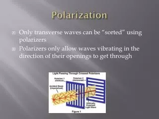
typical DWDM system with a nonlinearity probe ► CW probe is unaffected by linear effects / SPM ► otherchannelsare 10 Gbps OOK in 50 GHz grid
significant nonlinear depolarizationrapid (symbol-to-symbol) fluctuations of the SOP what is going on and is this a problem? SOP evolution(without amplifier noise)
► basics cross-polarization modulation (XPolM) ► statistical models ► XPolM and polarization multiplex ► experiments
nonlinear polarization effects known since at least 1969 ► e.g. Kerr shutter (Duguay and Hansen, APL, pp. 192+, 1969) XPolM first described in its „current version“ in 1995 ► Stokes space Manakov equation ► collision of two solitons ► Mollenauer et al., Optics Letters, pp. 2060+, 1995 many-channel formulation in 2006 ► Menyuk and Marks, JLT, pp. 2806+, 2006
Poincaré sphere probe channel DWDM interferers Stokes vector sum nonlinear rotation
► length (intensity) varies due to walk-off►(interferer and probe group velocity differs) ► direction (SOP) varies due to PMD► (interferer and probe birefringence differs) ► both effects are random various models have been proposed to describe this behavior (interferer) Stokes vectors are not constant
► Karlsson‘s statistical model (JLT, pp. 4127+, 2006) ► influence on PMD compensation ► mostly two-channel system, no PMD dependence ► diffusion model (Winter et al., JLT, pp. 3739+, 2009) ► SOPs evolve as random walk ► ensemble mean values only ► carousel model (Bononi et al., JLT, pp. 1903+, 2003) ► pump and probe rotate when both carry a mark ► two-channel system, no PMD
DWDM power/channel threshold for mean probe DOP=0.97 ► resonant dispersion map, 10 × 10 Gbps OOK interferers► @ 50 GHz spacing
depolarization of probe vs. number of 3 dBm interferers ► difficult to simulate, expensive to measure► saturates at about 20
a typical PolDM system ► selective upgrade: 10G NRZ » 100G PolDM RZ-QPSK ► fits into 50 GHz grid
detected field at y-Rx: ► otherwise crosstalk occurs from x to y and vice versa ► crosstalk increases with misalignment angle and with►length of field vector polarization DEMUX must be aligned to PolDM subchannels (visualization in Jones space)
XPolM causes symbol-to-symbol fluctuations around mean SOP ► cannot be compensated (again like XPM) modern coherent receivers can handle subchannel SOP changes with PMD time constants ► DCF abuse with a screwdriver: 280 µrad/ns(Krummrich and Kotten, OFC 2004, FI3)
field amplitude at y-Rx aligned subchannels interleaved subchannels time ► crosstalk is never zero because pulses at Rx are no longer RZ (accumulated GVD, PMD, noise) interleaving RZ-shaped symbols minimizes crosstalk generation
10 × 10G NRZ interferers w/ 100G PolDM-RZ-QPSK probe ► 256 ps/nm RDPS, 10 interferers, SSMF, no PMD ► power/channel threshold is reduced by up to 2 dB
the statistical ensemble (mean DOP = 0.975) ► DOPs and ROSNRs spread over large range ► for DOPs < 0.98 (0.97), ROSNR penalties become significant
Xie showed how PolDM interferers can cause negligible XPolM compared to single-polarization (PTL, pp. 274+, 2009) ► requires RZ pulse shape and subchannel interleaving ► neighboring half-symbol slots have orthogonal polarization states ► probe SOP oscillates but rotation does not accumulate
► onset of nonlinear penalties at much lower powers ► (near) saturation of penalties for large channel spacing (van den Borne et al., ECOC, 2004, Mo 4.5.5)
► saturation of penalties for large number of interferers (Renaudier et al., PTL, pp. 1816+, 2009)
► benefit of PolDM vs. OOK interferers (Bertran-Pardo et al., OFC, 2008, OTuM5)
► XPolM in DWDM systems causes depolarization ► diffusion model correctly predicts simulated behavior ► depolarization creates detrimental PolDM crosstalk ► can be reduced by interleaving PolDM subchannels slides available at http://www.marcuswinter.de/publications/ST2010