Download

1 / 24
240 likes | 524 Vues
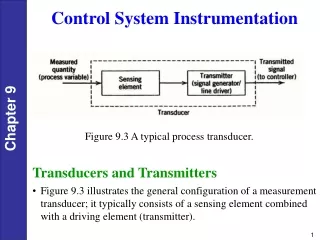
INTRODUCTION. Karachi Nuclear Power Plant ( CANDU type,137MWe) was designed in the mid 60's. The control and instrumentation (C

E N D
1. REPLACEMENT OF OBSOLETE INSTRUMENTATION & CONTROL IN KANUPP & CHALLANGES FACED.
2. INTRODUCTION Karachi Nuclear Power Plant ( CANDU type,137MWe) was designed in the mid 60�s. The control and instrumentation (C&I) of Nuclear Power Plants built during that period employed a combination of pneumatic and electronic system. These systems, based on analog concept.
The rapid advances in electronic technology has resulted in replacement of older system with new C&I. This has affected the nuclear power plants such as KANUPP that are still using C&I based on older technology. Obsolescence of C&I equipment has become a major concern for nuclear industry all over the world.
3. There are many aspects of growing obsolescence of existing C&I. The infrastructure that supported the older instrumentation has disappeared in the last three decades. Spare parts are no longer available. The availability of the plant has affected due to long maintenance period of C&I systems based on discrete components.
PAEC has started a project �Backfitting of C&I system with new technology in late 80�s but due to nuclear embargo on developing countries this project has been delayed more than ten year. INTRODUCTION
4. By the grace of GOD (Allah All mighty ) ultimately we have succeeded to get PLC�s based automation system and field and control room devices compatible to the automation system.
So far we have REPLACED 42 C&I Loops in 2004.
The remaining obsolete C&I would be replaced in long shutdown of 2006. INTRODUCTION
5. -Methodology to Replace Old C&I Plant personnel did not know the controllers transfer function. The transfer functions were determined by giving Step/Ramp signals and recording their outputs. The transfer function were determined by analyzing the performance curve of the controllers with theoretical curve of various transfer functions.
6. For more complex loops e.g. primary pressure control, blow-off control and boiler level control loops etc. The physical transfer functions were not available. When the scaling calculation applied on these physical equations and electronic equations obtained, it was found that gain and biases are different with those electronic equations which are implemented by existing control systems. Hence reverse engineering was performed on physical equations to know the exact equations in order to use these equations while replacing the loops. -Methodology to Replace Old C&I
7. After fulfilling the above, the comprehensive generic design specifications and ITB documents were prepared for replacement C&I of the plant. The generic specifications of 24VDC redundant UPS were also prepared, as modern I&C utilize 24VDC power supply.
International tender were floated to potential C&I vendors for NPP.
After thorough discussions with potential vendors and visiting there fabrication facilities, CEGELEC-ACEC, Belgium were selected as automation vendors and CEGELEC-Paris were selected as supplier for sub-supplier equipment/devices such as 24VDC UPS, process sensing transmitter, control valve positioners, hand/auto station, indicators, recorders and switches etc. -Methodology to Replace Old C&I
8. KANUPP has two types of loops:
Conventional C&I (measurement & close control loops) and safety C&I (Reactor protection and engineered safeguard loops).
Measurement loops = 72 (Loops list),
close control loops = 48, (Loops list),
Reactor protection = 49 (Loops list) and
Engineered safeguard loops = 15 (Loops list).
Total = 178 in first phase of replacement.
The loops covered under full scope are 300, the rest of the loops would be replaced in two years.
9. AC 132-16 programmable system (industrial version) has been selected for C&I conventional, keeping in view the following facts:
This system is being used by ACEC for backfitting of the obsolete C&I of Belgian NPPs and ACEC has developed this system for future NPPs.
All KANUPP loops functions can be met by the system.
Powerful diagnostic function are available to trace the faults in minimum possible time.
AC-132-16 programmable system (Class IE qualified version) is selected for C&I safety. The software used in the system is TNS186. This software is highly integrity software has been developed and designed according to international standards, ANSI/IEEE-ANS-7.4.3.2 of 1982 and IEC880 of 1986. This software is qualified by Belgian Nuclear Regulatory Authority (Vincotte) according to standard ISO9001. -Methodology to Replace Old C&I
10. Consequently the architecture were designed for conventional & safety C&I.
Based on these architectures, comprehensive list of sub-supplied equipment and automation system modules (conditioning cards, system modules, I/O modules) alongwith procurement specifications was prepared as per vendor design rule.
The above documents were sent to different suppliers for fabrication of the equipment and devices. -Methodology to Replace Old C&I
18. When the equipment were fabricated, we started the activities for architecture engineering and detailed design. The following documents were prepared:
Design Description.
Design specifications.
Elementary diagrams.
Wire list.
Updating of operating manuals.
Application programs.
Cable engineering.
Installation standards.
Electronics cabinets configuration diagrams.
Hand/auto stations configuration diagrams. -Methodology to Replace Old C&I
19. Control room panel engineering.
Marshalling cabinet design, interface devices & incoming and outgoing cable engineering.
Open loop test procedures.
Periodic test procedures for safety C&I.
Isolation procedures.
Removal of existing & Installation of new C&I devices procedures.
General architecture design description of C&I conventional.
General architecture design description of C&I safety.
Redundant Power supply to electronic/marshalling cabinet.
Grounding and shielding.
Reliability calculations for C&I safety. -Methodology to Replace Old C&I
20. Suppression and elevation calculations in view of new installation.
Detailed work plan/ pert showing activity and time duration.
Quality Assurance plans.
Jumper sheets.
Stability analysis for critical closed control loops with new hardware & software.
Additional windows in control room for detecting faults (measurement faults, controller faults, switchover, controller identification faults, general hardware faults).
Fault detection from control room to electronic room cabinet rows, faulty cabinet and faulty module, corrective action to remove the faults. -Methodology to Replace Old C&I
21. When fabrication of equipment is completed, ACEC and sub-supplies invite KANUPP personnel to accept the equipment. Dummy application program were prepared to test the complete range of system and devices. consequently, a team of KANUPP engineers has gone to Belgian and France.
Three types of test were performed:
To test measurement loops at CPU level, system modules, I/O modules and conditioning cards.
To test safety C&I on CPU level, system module, I/O modules and conditioning cards.
To test closed control loops at dedicated and intelligent controllers (MCI-As).
22. Comprehensive test procedure were prepared to test the whole range of our requirements.
18-electronic cabinets were checked for this configuration as per our requirements. Some of the non conformance were found which were conveyed to ACEC specialist. After rectification the actual test were performed.
During actual testing some of the major NCR were found e.g. controllers deviation was limited at �5% whereas our requirement was �100% deviation signal. In this case the EPROM of all the controller were changed. Some of the modules found not functioning these were also changed.
23. Similarly at sub-supplies factories, it was found that all level transmitter were calibrated in direct acting mode whereas our requirements was of reverse acting mode.
At marshalling cubicle factory, many flaws were found in internal wiring which were rectified by our team.
At indicators factory, some of the indications were not functioning properly, on our advise they rectified the problems.