Download
1 / 30
330 likes | 531 Vues
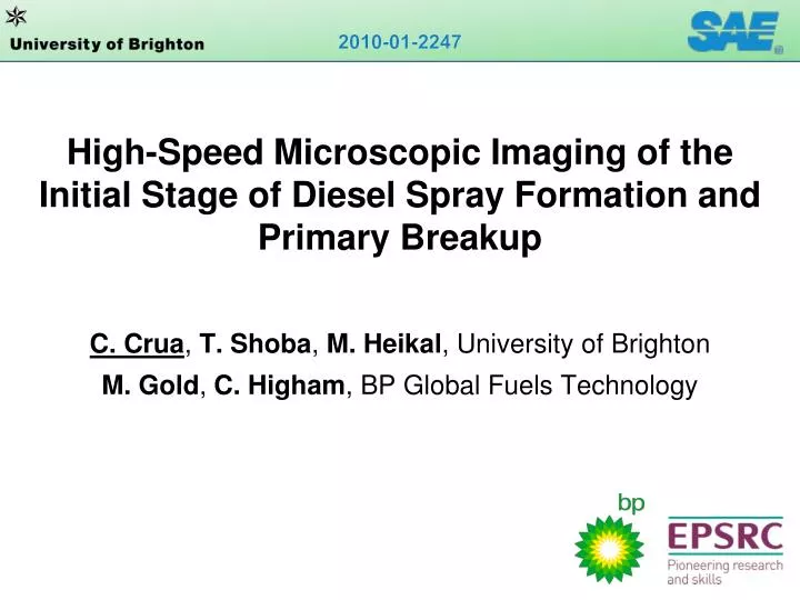
High-Speed Microscopic Imaging of the Initial Stage of Diesel Spray Formation and Primary Breakup . C. Crua , T. Shoba , M. Heikal , University of Brighton M. Gold , C. Higham , BP Global Fuels Technology. Research objectives. Improve understanding of:

E N D
High-Speed Microscopic Imaging of theInitial Stage of Diesel Spray Formation andPrimary Breakup C. Crua, T. Shoba, M. Heikal,University of Brighton M. Gold, C. Higham, BP Global Fuels Technology
Research objectives • Improve understanding of: • Initial stage of diesel spray formation • Breakup mechanisms of jet and ligaments
Optical diagnostic technique • Techniques considered: • High-speed video Resolution too coarse • Doppler anemometry Slow; Dispersed spherical droplets only • Long-range microscopic imaging Lighting is difficult
Microscopic imaging of diesel sprays Badock, Wirth, Fath, Leipertz (1999) Heimgärtner , Leipertz (2000) Roisman, Araneo, Tropea (2007) Bae, Kang (2005)
Technique development Pulsed laser (~ 6 ns) Laser + diffuser (~ 20ns) Flood light Spark light (~ 500 ns) • Flood lights: Motion blurring, not enough light • Spark light: Short exposure but still some motion blurring • Pulsed laser: Short exposure but speckling artefact • Pulsed laser + diffuser: Non-homogeneous scattering • Pulsed laser + diffuser + shadowgraphy: Correct exposure
Non-evaporative test conditions • Static diesel spray rig • Ambient pressure & temperature • Quiescent air motion • Allows to develop experiments off engine
Simultaneous micro & macroscopic imaging Light source Microscope Camera Camera
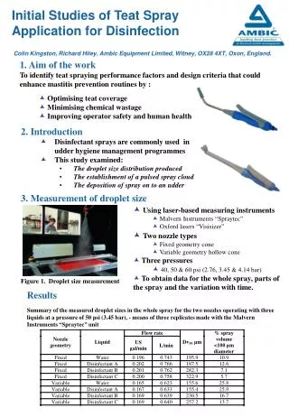
Spray microscopy test conditions • Field of view: 768 x 614 µm (1280 x 1024 pixels) • Injection pressures: 400, 1000, 1600bar • Ambient pressure: atm • Spatial locations: 0 to 5 mm in 0.5 mm increments • 6 to 30 mm in 4 mm increments
Initial stage of diesel spray formation 135 µm Spheroidal cap Surface ripples Stagnation point Spheroidal cap VCO Delphi DFI1.3, Pinj = 400 bar, ICP = 1 atm, exp = 20ns, 0.600 µm/pix
Initial stage of diesel spray formation Pinj = 400 bar, ICP = 1 atm, exp = 20ns, 0.600 µm/pix
Ligament formation and primary breakup0.5 – 1.0 mm from nozzle Pinj = 400 bar, ICP = 1 atm, exp = 20ns, 0.600 µm/pix
Ligament formation and primary breakup1.0 – 1.5 mm from nozzle Pinj = 400 bar, ICP = 1 atm, exp = 20ns, 0.600 µm/pix
18.5mm downstream 200µs later
Ligaments ahead of the jet Roisman, Araneo, Tropea (2007)
Questions arising • Temporal evolution of initial jet? • Origin of ligaments ahead of jet? • Breakup mechanisms within initial 1 mm?
Ultra high-speed micro & macroscopic video Light source Microscope u-HS camera HS camera 200 million fps, 5ns exp, 1280x960 pixels 16 frames, intensified 100k fps, 1µs exp, 200x60 pixels Non-intensified
Evaporative test conditions Rapid Compression Machine – Ricardo Proteus • 4, 6, 8 MPa pressure at TDC • Up to 200 MPa fuel injection pressure • 540 K estimated temperature at TDC • Operated at 500 rpm • Quiescent air motion at start of injection (no swirl)
Central ligament ahead of the spray 995 µm 746 µm Spheroidal cap is translucent Vapour phase Residual fuel Jet and central ligament are opaque Liquid phase Fresh fuel Ligament penetrates faster than jet Less resistance along centreline Pinj = 400 bar, ICP = 40 bar, exp = 20ns, dt = 2µs, 0.777 µm/pix
Central ligament ahead of the spray 995 µm 746 µm Pinj = 400 bar, ICP = 40 bar, exp = 20ns, dt = 2µs, 0.777 µm/pix
Ligaments ahead of the spray D = 135 µm Spheroidal cap (residual fuel) Corolla • Trapped fuel pushed out by fresh fuel • Less resistance along centreline • Vortex ring motion • Surface ripples • shear layer 127 µm ~D Jet (fresh fuel) 23 µm Ligament
Effect of spheroidal cap on jet velocity Jet without cap 22 m/s 36 m/s Jet: 44 m/s Cap: 14 m/s Pinj = 400 bar, ICP = 80 bar, exp = 40ns, dt = 2µs, 0.777 µm/pix
Breakup mechanisms within initial 1 mm Pinj = 400 bar, ICP = 1 atm, exp = 40ns, dt = 5µs, 0.777µm/pix
Breakup mechanisms within initial 1 mm Pinj = 400 bar, ICP = 1 atm, exp = 20ns, 0.600µm/pix
Further developments • Ultra-high speed drop size & velocity? • Need: - Higher resolution (non-intensified) images • - Higher magnification factor
Double-shot microscopic imaging samples 337 µm 446 µm Confirms vortex ring motion in the vaporised fuel VCO, Pinj = 400 bar, ICP = 40 bar, exp = 20ns, dt = 0.5µs, 324nm/pix
Double-shot microscopic imaging samples 337 µm 446 µm Vaporised trapped fuel with sac-type Delphi DFI 1.5, 1000 bar Pinj = 1000 bar, ICP = 40 bar, exp = 20ns, dt = 0.5µs, 324nm/pix
Next step: Droplet sizing 10.5 – 11.0mm 18.5 – 19.0mm Spray periphery Spray centre Spray centre Spherical droplets represent a small proportion of fuel volume
Next step: Droplet sizing • Further work: • Particle tracking for single droplet velocity and size
Conclusions • Spray formation • Residual fuel remains in the nozzle orifice between injections • (VCO and sac-type nozzles, latest injector generation) • Trapped fuel affects the dynamics of spray formation • (evaporative and non-evaporative conditions) • Degradation of residual fuel internal deposit • Breakup mechanisms • Breakup processes observed & described near nozzle • Spherical droplets represent a small proportion of total fuel volume • (need techniques for aspherical droplet sizing and velocimetry)
High-Speed Microscopic Imaging of theInitial Stage of Diesel Spray Formation andPrimary Breakup C. Crua, T. Shoba, M. Heikal,University of Brighton M. Gold, C. Higham, BP Global Fuels Technology