Download
1 / 10
100 likes | 167 Vues
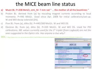
Mice Beam Stop (end of DSA). Details of the current Layout and how it was arrived at. Original idea. Fig.1.

E N D
Mice Beam Stop(end of DSA) Details of the current Layout and how it was arrived at. Mice Beam Stop Geoff Barber
Original idea Fig.1 The original layout for a beam stop, Fig.1, was put before Paul Wright last week but was rejected. His comment was that although we had 700mm of various materials in front of the beam there was very little material to the side to stop any scattering Fig.2 Fig.2 Mice Beam Stop Geoff Barber
Paul Wrights Requirements(as understood by me) The original layout had 700 mm of material in the forward direction, therefore Paul would also want to see the same amount of material at the sides. This could mean in its simplest form a block as shown in Fig.3 or if we take it literally it will be as shown in Fig.4 Fig.3 Fig.4 Mice Beam Stop Geoff Barber
What does this mean • To recap the original layout had 700 mm of material in the forward direction but only 100mm material to the side. Even so this gave the block a weight of 1500kgs. The block as now required would weigh in the region of • Plain Design = 8,800kgs • Onion Design = 6148kgs • It is impractical to move this weight ‘as routine’, so an alternative scheme is required. Mice Beam Stop Geoff Barber
“An Alternative Scheme” To reduce the weight that needs to be moved and to allow the installation to be carried out in the required timescale the proposal is to only move a part of the beam stop. This is acceptable to Paul Wright, it was actually his suggestion originally. This scheme uses an ‘off the shelf (5-6week delivery)’ scissor lift that we can adapt easily to fit our requirements. Mice Beam Stop Geoff Barber
Proposed Baseline Layout The sliding beam stop is stepped to avoid straight line gaps. This also guides the block and will stop it falling forward. The total weight of the sliding block is 1,898kgs Mice Beam Stop Geoff Barber
Scissor Lift The specification of the scissor lift chosen is:- Capacity 3000kg Travel 820mm Footprint 1350x800mm Closed Height 250mm Price £3600 + Vat Delivery 5-6 weeks Scissor lift shown is a 2 stage we will be using a single stage unit. A 3000kg lift was chosen to allow for a slight ‘off-centre’ lift and it also gives a little flexibility as the layout evolves to its final configuration Mice Beam Stop Geoff Barber
Scissor Lift Failsafe.(Designed By Us) The scissor lift is powered using Hydraulics and under normal operation the company can supply a level sensor that will detect if the table drops 5mm’s and adjust the height. The system has to be ‘wired’ into the hall safety system and so the position of the beam stop is known at any given time. However, should the hydraulics fail I feel it would be good to have the stop held up so access to the hall (to effect a repair) can be done without disruption to ISIS. Speaking to the company, this is possible using a ratchet type system which follows the scissor arm on the upward stroke but would need a mechanical activation to allow the down stroke. Positive activation To release Adjustment for beam stop height Mice Beam Stop Geoff Barber
Collimator The size of the complete beam stop structure means that the collimator will need to be relocated. Depending on the ‘Z’ dimension of the collimator unit (shown in red) it may be possible to site it after the beam stop. There will be approximately 300 - 400mm between the guards of the beam stop and the face of the mirror plate of Q7. If it is slim enough it could sit on the steelwork that holds up the stationary component of the beam stop. Mice Beam Stop Geoff Barber
Summary There are a few details still to be worked out but I don’t see any show stoppers If we are to meet the very tight time constraints a decision needs to be arrived by 23 April 2008 Drawings will need to be prepared so that quotes can be sought and orders placed. Control systems will have to be worked out and agreed with the relative parties Controls Brian Martlew PPS John Alexander/Craig Macwaters Mice Beam Stop Geoff Barber