Download
1 / 78
780 likes | 875 Vues
DALHM D evelopment and A nalysis of L eft H anded M aterials. FORTH, Crete, Greece Bilkent University, Ankara, Turkey Imperial College, London, England. 2nd year Meeting July 29-30, 2004 Crete, Greece. Computational Methods. Plane wave expansion method (PWE)

E N D
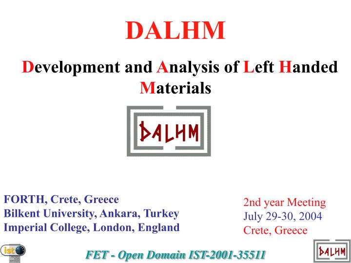
DALHM Development and Analysis of Left Handed Materials FORTH, Crete, Greece Bilkent University, Ankara, Turkey Imperial College, London, England 2nd year Meeting July 29-30, 2004 Crete, Greece
Computational Methods • Plane wave expansion method (PWE) R. Moussa, S. Foteinopoulou & M. Kafesaki • Transfer matrix method (TMM) Th. Koschny, R. Penciu & P. Markos • Finite-difference-time-domain-method (FDTD) M. Kafesaki, R. Moussa, & S. Foteinopoulou • Effective medium theories E. N. Economou, Th. Koschny • Microwave studio T.O.Gundogdu, R. Penciu, M. Kafesaki & Lei Zhang
New discretization scheme: Symmetry is preserved This new symmetric material discretization completely eliminates the problem of the off-diagonal terms in the transfer matrix approach for sufficiently accurate computation. So we have successfully implemented a new discretization scheme that gives no off-diagonal terms.
Typical LHM behavior Resonance and anti-resonance
Analytic model for the electric and magnetic response of SRRs
Analytic model of the electric and magnetic response of LHMs PRL (accepted, 2004)
Electric response of wires Electric response of cut wires Electric and magnetic response of SRR Electric response of LHM E and M response of LHM
LHM Design used by UCSD, Bilkent and ISU LHM SRR Closed LHM T Substrate GaAs eb=12.3 f (GHz) 30 GHz FORTH structure with 600 x 500 x 500 mm3
Left-Handed Materials t r1 d r2 w SRR Parameters: r1=2.5 mm, r2=3.6 mm, d=w=0.2mm t=0.9 mm Parameters: ax=9.3 mm ay=9mm az=6.5 mm Nx=15 Ny=15
Transmission data for open and closed SRRs Magnetic resonance disappears for closed SRRs Bilkent & Forth
Effective wp of closed SRRs & wires is much lower than wp of the wires. Bilkent & Forth
Best LH peak in a left-handed material Peak at f=4 GHz =75 mm much larger than size of SRR a=3.6 mm Losses: -0.3 dB/cm Bilkent & Forth
Experiment Theory Bilkent & Forth
Retrieval parameters for Bilkent structure Bilkent & Forth
Transmission spectra in the low frequency region for 3 unit cells
Transmission S21 in the lower and higher region (1 unit cell)
Electric and Magnetic Response of SRRs and LHMs • Electric and Magnetic Response are independent. • One can change the magnetic response without changing • the electric response. • GHz and THz magnetic response in artificial structures! • The SRR has strong electric response. It’s cut-wire like. • Effective electric response of LHM is the sum of wire and SRR. • Effective wp of the LHM is much lower than wp of the wires. • There are “phony” LH peaks when wp < wm PRL (accepted, 2004)
Electric coupling to the magnetic resonance APL 84, 2943 (2004)
Magnetic response at 100 THz, almost optical frequencies 10 S. Linden & M. Wegener, Karlsruhe
Magnetic response at 100 THz, almost optical frequencies S. Linden & M. Wegener, Karlsruhe
Magnetic response at 100 THz, almost optical frequencies S. Linden & M. Wegener, Karlsruhe
4 cases of different propagation and polarization for single ring cell = 2.5mm gap azimuthal = 0.3mm ring outer side length = 2.2mm ring width = 0.2mm sub thickness =0.25mm
Transmission and retrieved parameters k in the plane gives a negative region, otherwise remains positive even though a gap appears in the transmission spectra when E field is along the ring gap.
Sub thickness dependence the closer the separated opposed rings are, the weaker the electric coupling is.Here are shown transmission spectra and when the thickness are chosen to be 0.25mm, 0.125mm and 0.075mm
cell = 2.5mm in X/Y/Z ring side length = 2.2mm wire width = 0.2mm ring width = 0.2mm opposed ring separation = 0.2mm this structure is symmetric in 3D and also behaves almost the same for different polarizations see black and red curve below. 3D Rings & Wires
n and there are multiple negative index regions from the retrieval code
e) b) c) d) a) Going to multi-gap structures (1) Reason: requirement for higher symmetry, for use in 3D LH structures • better than (b) (wider SRR dip); (c) better than (d) (stronger dip); (e) like the conventional SRR but weaker dip (for large separation) • Problem: Increase of m (m close to0 ) • Gaps act like capacitors in series: m2(n gaps)~ n m2(1 gap)
Going to multi-gap structures (2) Solution: Make the gaps smaller or change the design Up to a point Improvements? Only the left one
a) c) b) Promising multi-gap structures from 1D study (a): Detailed study on progress (in 1D) (b): Not studied in detail yet (c): Good LH T 3D structures a) b) c) Best combination: (b)+(c)


![ADD M [A] [A] + [[H-L]]](https://cdn3.slideserve.com/5603322/slide1-dt.jpg)