Download
1 / 58
580 likes | 713 Vues
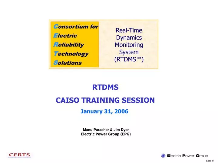
C onsortium for E lectric R eliability T echnology S olutions. Real-Time Dynamics Monitoring System (RTDMS™). RTDMS CAISO TRAINING SESSION. January 31, 2006. Manu Parashar & Jim Dyer Electric Power Group (EPG ). Phasor Technology – Overview

E N D
Consortium for Electric Reliability Technology Solutions Real-Time Dynamics Monitoring System (RTDMS™) RTDMS CAISO TRAINING SESSION January 31, 2006 Manu Parashar & Jim Dyer Electric Power Group (EPG)
Phasor Technology – Overview The Importance of Using Synchronized Data Review of Some WECC Events CAISO Real-Time Dynamics Monitoring System Project Objectives System Architecture What the System Operator Will See RTDMS Visualization Architecture Navigation Within RTDMS Displays Client Support RTDMS Application Demo Agenda
Generation Load What Causes Power to Flow on the Grid DC power system - Power flows from a point of high voltage to a point of low voltage. AC power system - Power flows from a point of high voltage angle to a point of low voltage angle. The higher the angle the greater the power flow.
Generation Load What Causes Voltage Angle to Increase • What can cause the voltage angle to increase? • Increased scheduled power transfers between source and sinks (increasing the prime mover [e.g. steam] in source generators and decrease on sink generators). • Transmission lines removed (forced or scheduled) from service between source and sink, without adjusting schedules. • Loss of generation in the sink area.
Eastern Interconnection - Angle Separation on 8-14-03 115 degrees 45 degrees 25 degrees 12 degrees
Power System Dynamics • Mechanical Analogy for Power System Dynamics • Balls analogous to generators with different inertia • Strings analogous to the physical power grid • Pendulum swings analogous low-frequency oscillations observed by Phasor Measurement Units (PMUs) • Oscillations may either decay or grow implying stability or instability respectively
What Phasor Measurements are all about Phasor Overview “Reference 60Hz Signal using GPS time signal” COB Phase Magnitude
What Phasor Measurements are all about (cont.) Pure 60Hz Signal Strobe Light Analogy Decelerating System Accelerating System
What Phasor Measurements are all about (cont.) System Wide “Snapshot” Across Power Grid Leading phase angles Lagging phase angles Leading phase angles Reference bus (0 Degrees)
Importance of PMU Data Synchronization phase angle difference using synchronized data phase angle difference using unsynchronized data with 1 second mismatch
What Phasor Measurements are all about (cont.) Networking - Most stability events, involve a widespread area, and involve oscillations and control interactions between neighboring utilities and geographic operational regions. This dictates the need for multiple recording devices across the transmission grid. Time Synchronization - Phasor measurements are time-stamped using the global satellite positioning system so that measurements from across the interconnection can be precisely aligned for comparison against one another.
What Phasor Measurements are all about (cont) The Primary Hardware Elements in a Phasor Network are: Phasor Measurement Unit (PMU) – PMUs are located at key substations and measures and are capable of gathering better data at higher sampling rates than analog monitoring devices. The PMU time stamps the local frequency, voltage and line currents at a rate of 30 to 60 times per second. The voltage and current data is used to calculate MW and MVAR flows on key lines. Substation PMU phasor data is transmitted to a PDC at a central location.. Phasor Data Concentrator (PDC) – Receives, integrates, and stores phasor signals from remote PMUs. Can also exchange records with PDCs at other locations. One of the primary functions of the PDC is to perform data synchronization.
The use of phasor technology allows the industry to take high resolution “snapshots” of what is happening throughout the Western Interconnection grid and evaluate the grids performance during system events. System operators and planners can use data gathered by PMUs for a host of applications, including:• State estimation • Real-time wide area monitoring • Validation of power system models • Transient instability protection and fault location systems Phasor Technology – Industry Uses
Value of Phasor Technologies - Example Actual System Performance WECC’s Experience Comparison of model simulation system performance predictions prior to the WECC’s August 10, 1996 blackout (lower panel) and conditions actually recorded by phasor technologies (upper panel) showed that the planning models were not able to accurately capture underlying causes of the blackout The WECC has since modified their simulation models to better represent actual system performance. Model Simulation - PredictedSystem Performance
Actual WECC Phasor Data Events
Location: Western Interconnection Date/Time: Friday, August 4, 2000, 7:56PM High Static Stress and Low Dynamic Stress System Conditions: System was operating with an angle greater than 90 degrees between Devers Substation (Palm Springs, Ca.) and Grand Coulee Power Plant (near Spokane, Wa.), a distance of over 1,000 miles A 500 kV tie-line exporting power from British Columbia to Alberta, Canada tripped Loss of line resulted in increased flows by 450 MW The dynamic stress between Devers and Grand Coulee increased to 108 degrees (an 18 degree increase) System oscillated for about 60 seconds showing low damping WECC Event - # 1
WECC Event - # 1 J. Balance, B. Bhargava, G.D. Rodriquez, “Use of Phasor Measurement System for Enhancing AC-DC Power System Transmission Reliability and Capacity.”
WECC Event # 2 • Location: Western Interconnection • Date/Time: Tuesday, October 8, 2002, 3:38PM • Abnormal Interconnection Frequency: 59.62 Hz (380 mHz) • System Conditions: • An AC line fault occurred in the northwest tripping three 500 kV lines • SPS operated by applying the 1400 MW Chief Joseph break and tripping 2800 MW of generation in northern WECC system. • The frequency dropped to 59.620 Hz.
WECC Event # 3 • Location: Western Interconnection • Date/Time: Sunday, January 15, 2006, 00:24AM • Generator Trip (System Frequency Response Captured by RTDMS) • System Conditions: • NEW Colstrip Unit 1 relayed while carrying 240 MW • System frequency deviated from 59.995Hz to 59.947Hz • Recovered to 59.961Hz by governor action • Returned to pre-disturbance level at 00:29
WECC Event #3 RTDMS Event File Name “20060115_002424” Identify Trip near Colstrip PMU Alarm log indicating Frequency Transient detected at the Colstrip PMU and the time of the event System Frequency Response
WECC Event #3 (Frequency Response) January 15, 2006 (CAISO Log) 01/15/2006 - 00:24 System frequency deviated from 59.995Hz to 59.947Hz and recovered to 59.961Hz by governor action when NWE Colstrip Unit 1 relayed while carrying 240 MW. System frequency returned to pre-disturbance level at 00:29. 59.991Hz f = 30mHz Identify Trip near Colstrip PMU 59.961Hz 1840MW Jan 15, 2005 00:24:24 AM P = 240MW = P/f = 800MW/0.1Hz 1600MW
Any Questions About Phasor Technology?
Develop a Real-Time Phasor Monitoring Prototype System for use by system operators at utilities, ISOs and reliability coordination centers. Enable system operators to gain familiarity with phasor technology for reliability monitoring and real-time operations. Learn to utilize phasor data to recognize normal and abnormal conditions, and assess grid stress. Provide system operators with real-time wide area information to increase situational awareness to avoid August 10, 1996 type blackouts. Monitor across the entire Western Interconnection (WI) for reliability, stability, system dynamics, and other key metrics using time synchronized phasor data. Enable system operators to evaluate and provide feedback on metrics monitored, visualization formats, functionality and displays. Project Objectives for RTDMS Applications
CAISO RTDMS System Architecture Data Acquisition - Data Reading - Data Cleansing - Data Processing Data Management - Short-Term Buffer for RT Monitoring and Alarming - Historical Data for Trending/Reporting Remote Monitoring Clients - Data Retrieval - RT Monitoring & Alarming - Trending & Reporting
Wide Area View of WECC – Key metrics at selected locations and transmission corridors. Key Metrics Include – System frequency, voltages, phase angles and angle differences between major sources and sinks Violation of Key Thresholds (defined limits) – Visual alarming (color coded) Rapid Changes in Metrics - Visual alarming Identify System Anomalies RTDMS – What will the System Operator See?
How To Navigate Around The RTDMS Screens
RTDMS Visualization Architecture Real-Time Monitoring Mode Offline Analysis Mode
Four-Panel Display Major Functions Configuration/Help Functions Display Tabs Real-Time Monitoring Tracking/ Comparison Tracking/ Analysis Date/Time Scrolling/Tabular Text Text Box Navigation Icons
Sample Four-Panel Display Monitor : • voltage angles and magnitudes • color coded • quickly identify low or high voltage regions compare angles selected historical tracking and comparison over specified time duration System Status
Navigation Tools Selection Arrow Reposition Zoom In/Out Pick to Move Text Click on the cross arrows with the pointer, move the cursor to the text label, click the left mouse and drag the text label to the desired location in the panel Pick to Display Data Click on the arrow within the question mark to select data within the plot or diagram This is the default Navigation tool. Selecting this tool allows the user to click and move through the different plots and data tables Rubber Band Zoom Click the magnifying glass with the box in the background, place mouse within the plot or diagram and left click to select the zoom desired With the mouse on the image hold the button and slide the mouse down or to the left to reduce the size of the image or move the mouse up or to the right to increase the size of the image. Restore to Original Size Click on the double plot icon and click on the appropriate panel to restore the plot or diagram to its original size Click the cross arrows, move the cursor to the viewing panel, click the left mouse and drag the object to the desired location in the panel
Click to remove “check” mark Auto Refresh, Freeze and Replay Real-Time Streaming Data (Auto Refresh) Freeze Data When “check” mark is removed the current data is held Replay Data Toggle Switch between Real-Time and Replay Mode Auto-Forward Auto-Rewind
RTDMS Property Editor • Change the maps in geographic displays • Modify font settings of titles, axis labels, legend labels, identifiers, text values etc • Change graphics Properties Adjust legends – their thresholds and associated colors
RTDMS – Frequency Transient Example Alarm log indicating Frequency Transient detected at the Colstrip PMU and the time of the event Identify Trip near Colstrip PMU Frequency response at Colstrip PMU
CAISO RTDMS Functionalities Summary RTDMS Functionalities at CAISO: • Includes BPA, SCE, WAPA, and PGE phasor data shown in real-time • Server-Client architecture (Multi-user capability) • Geographic visualization on Voltages, Angle Differences, Frequency, MW & MVAR • End user configurability • Replay capability • Real-time alarming and event detection • Event archiving and playback
System Support and Help Tab
Contact Information • Manu Parashar • Office: (626) 685-2015 ext 130 • parashar@electricpowergroup.com
Any Questions Before We Move On To The Demo?
Start RTDMS Client Application Frequency (Response) Monitoring Display (default)