Download
1 / 20
200 likes | 340 Vues
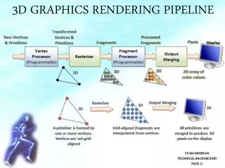
The Rendering Pipeline. CS 445/645 Introduction to Computer Graphics David Luebke, Spring 2003. Admin. Call roll Assignment 1. Transform. Illuminate. Transform. Clip. Project. Rasterize. Recap: The Rendering Pipeline. Model & Camera Parameters. Rendering Pipeline. Framebuffer.

E N D
The Rendering Pipeline CS 445/645Introduction to Computer Graphics David Luebke, Spring 2003
Admin • Call roll • Assignment 1 David Luebke 210/10/2014
Transform Illuminate Transform Clip Project Rasterize Recap: The Rendering Pipeline Model & CameraParameters Rendering Pipeline Framebuffer Display David Luebke 310/10/2014
Recap: The Rendering Pipeline Scene graphObject geometry • Result: • All vertices of scene in shared 3-D “world” coordinate system • Vertices shaded according to lighting model • Scene vertices in 3-D “view” or “camera” coordinate system • Exactly those vertices & portions of polygons in view frustum • 2-D screen coordinates of clipped vertices ModelingTransforms LightingCalculations ViewingTransform Clipping ProjectionTransform David Luebke 410/10/2014
Y X Z Recap: Transformations • Modeling transforms • Size, place, scale, and rotate objects parts of the model w.r.t. each other • Object coordinates world coordinates Y Z X David Luebke 510/10/2014
Recap: Transformations • Viewing transform • Rotate & translate the world to lie directly in front of the camera • Typically place camera at origin • Typically looking down -Z axis • World coordinates view coordinates David Luebke 610/10/2014
Recap: Transformations • Projection transform • Apply perspective foreshortening • Distant = small: the pinhole camera model • View coordinates screen coordinates David Luebke 710/10/2014
¢ q - q é ù é ù é ù X cos sin X = ê ú ê ú ê ú ¢ q q Y sin cos Y ë û ë û ë û Recap: Transformations • All these transformations involve shifting coordinate systems (i.e., basis sets) • That’s what matrices do… • Represent coordinates as vectors, transforms as matrices • Multiply matrices = concatenate transforms! David Luebke 810/10/2014
Rendering: Transformations • Homogeneous coordinates: represent coordinates in 3 dimensions with a 4-vector • Denoted [x, y, z, w]T • Note that w = 1 in model coordinates • To get 3-D coordinates, divide by w:[x’, y’, z’]T = [x/w, y/w, z/w]T • Transformations are 4x4 matrices • Why? To handle translation and projection David Luebke 910/10/2014
The Rendering Pipeline: 3-D Scene graphObject geometry • Result: • All vertices of scene in shared 3-D “world” coordinate system • Vertices shaded according to lighting model • Scene vertices in 3-D “view” or “camera” coordinate system • Exactly those vertices & portions of polygons in view frustum • 2-D screen coordinates of clipped vertices ModelingTransforms LightingCalculations ViewingTransform Clipping ProjectionTransform David Luebke 1010/10/2014
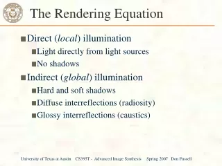
Rendering: Lighting • Illuminating a scene: coloring pixels according to some approximation of lighting • Global illumination: solves for lighting of the whole scene at once • Local illumination: local approximation, typically lighting each polygon separately • Interactive graphics (e.g., hardware) does only local illumination at run time David Luebke 1110/10/2014
The Rendering Pipeline: 3-D Scene graphObject geometry • Result: • All vertices of scene in shared 3-D “world” coordinate system • Vertices shaded according to lighting model • Scene vertices in 3-D “view” or “camera” coordinate system • Exactly those vertices & portions of polygons in view frustum • 2-D screen coordinates of clipped vertices ModelingTransforms LightingCalculations ViewingTransform Clipping ProjectionTransform David Luebke 1210/10/2014
Rendering: Clipping • Clipping a 3-D primitive returns its intersection with the view frustum: David Luebke 1310/10/2014
Rendering: Clipping • Clipping is tricky! • We will have a whole assignment on clipping In: 3 vertices Out: 6 vertices Clip In: 1 polygon Out: 2 polygons Clip David Luebke 1410/10/2014
Transform Illuminate Transform Clip Project Rasterize The Rendering Pipeline: 3-D Model & CameraParameters Rendering Pipeline Framebuffer Display David Luebke 1510/10/2014
Modeling: The Basics • Common interactive 3-D primitives: points, lines, polygons (i.e., triangles) • Organized into objects • Collection of primitives, other objects • Associated matrix for transformations • Instancing: using same geometry for multiple objects • 4 wheels on a car, 2 arms on a robot David Luebke 1610/10/2014
Modeling: The Scene Graph • The scene graph captures transformations and object-object relationships in a DAG • Nodes are objects; • Arcs indicate instancing • Each has a matrix Robot Head Body Mouth Eye Leg Trunk Arm David Luebke 1710/10/2014
Modeling: The Scene Graph • Traverse the scene graph in depth-first order, concatenating transformations • Maintain a matrix stack of transformations Robot Visited Head Body Unvisited Leg Mouth Eye Trunk Arm MatrixStack Active Foot David Luebke 1810/10/2014
Modeling: The Camera • Finally: need a model of the virtual camera • Can be very sophisticated • Field of view, depth of field, distortion, chromatic aberration… • Interactive graphics (OpenGL): • Camera pose:position & orientation • Captured in viewing transform (i.e., modelview matrix) • Pinhole camera model • Field of view • Aspect ratio • Near & far clipping planes David Luebke 1910/10/2014
Modeling: The Camera • Camera parameters (FOV, etc) are encapsulated in a projection matrix • Homogeneous coordinates 4x4 matrix! • See OpenGL Appendix F for the matrix • The projection matrix premultiplies the viewing matrix, which premultiplies the modeling matrices • Actually, OpenGL lumps viewing and modeling transforms into modelview matrix David Luebke 2010/10/2014