Download
1 / 46
540 likes | 885 Vues
Spine Advanced Imaging. By Prof. Stelmark. ATLAS (C1)

E N D
Spine Advanced Imaging By Prof. Stelmark
ATLAS (C1) The first cervical vertebra, the atlas, a name derived from the Greek god who bore the world upon his shoulders, least resembles a typical vertebra. Anteriorly, there is no body but simply a thick arch of bone called the anterior arch. The anterior arch includes a small anterior tubercle.
AXIS (C2) The most distinctive feature of the second cervical vertebra, the axis, is the clinically important dens or odontoid process, the conical process that projects up from the superior surface of the body.Embryologically, the dens is actually the body of C1, but it fuses to C2 during development. Therefore, it is considered part of C2 in mature skeletons.
Radiographic demonstration of the relationship of C1 to C2 and the relationship of C1 to the base of the skull is clinically important because injury this high in the spinal canal can result in serious paralysis and death. Normally, articulations between C2 and C1, the zygapophyseal joints, are perfectly symmetric. Accordingly, the relationship of the dens to C1 also must be perfectly symmetric. Both injury and improper positioning can render these areas asymmetric. For example, rotation of the skull can alter the symmetry of these spaces and joints, thus imitating an injury. Therefore, accurate positioning for this region is essential
A.Centrally located dens B.Left transverse process of C1 C.Left lateral mass of C1 D.Inferior articular surface of C1 E.Left zygapophyseal joint surface of C2 F.Body of C2 G.Right superior articular
AP “OPEN MOUTH” PROJECTION—C1 AND C2: CERVICAL SPINE Warning: Do not attempt any head or neck movement if cervical trauma is possible without first consulting with a physician who has reviewed a horizontal beam lateral radiograph. Pathology Demonstrated Pathology (particularly fractures) involving C1 and C2 and adjacent soft tissue structures. Demonstrates odontoid and Jefferson fractures.
Patient Position Position patient in the supine or erect position with arms by sides. Place head on table surface, providing immobilization if needed. Part Position • Align midsagittal plane to CR and midline of table. • Adjust head so that, with mouth open, a line from lower margin of upper incisors to the base of the skull (mastoid tips) is perpendicular to table and/or IR, or angle the CR accordingly. • Ensure that no rotation of the head or thorax exists. • Ensure that mouth is wide open during exposure. (Do this as the last step and work quickly, because it is difficult to maintain this position.)
Central Ray • CR perpendicular to IR, directed through center of open mouth • Image receptor centered to CR • Minimum SID of 40 inches (100 cm) Collimation Close four-sided collimation to area of interest, approximately 4 × 4 inches or 10 × 10 cm Respiration Suspend respiration. Note: Make sure that when patient is instructed to open the mouth, only the lower jaw moves. Instruct the patient to keep the tongue in the lower jaw to prevent its shadow from superimposing the atlas and axis. If the upper dens cannot be demonstrated, perform Fuchs
Structures Shown: • Dens (odontoid process) and vertebral body of C2, lateral masses of C1, and zygapophyseal joints between C1 and C2 should be clearly demonstrated through the open mouth.
AP OR PA PROJECTION FOR C1-C2 (DENS): CERVICAL SPINE Fuchs Method (AP) Warning: Do not attempt this head or neck movement if cervical trauma is possible without first consulting a physician who has reviewed a lateral cervical radiograph. Pathology Demonstrated Pathology involving the dens and surrounding bony structures of the C1 ring is demonstrated.
Patient and Part Position • Supine (AP) or prone (PA) with midsagittal plane aligned to CR and midline of table and/or IR • Elevate chin as needed to bring MML (mentomeatal line) near perpendicular to tabletop (adjust CR angle as needed to be parallel to MML). • Ensure that no rotation of head exists (angles of mandible equidistant to tabletop). • Center IR to projected CR. • CR is parallel to MML, directed to inferior tip of mandible.
Collimation Close four-sided collimation to C1 to C2 region Respiration Suspend respiration. Structures Shown: • Demonstrates the dens (odontoid process) and other structures of C1 to C2 within the foramen magnum.
AP “WAGGING JAW” PROJECTION: CERVICAL SPINE Ottonello Method Warning: Do not attempt this head or neck movement if cervical trauma is possible without first consulting a physician who has reviewed a lateral cervical radiograph. Pathology Demonstrated Pathology involving the dens and surrounding bony structures of the C1 ring, as well as the entire cervical column, is demonstrated.
Part Position • Align midsagittal plane to CR and midline of table and/or IR. • Adjust head so that a line drawn from lower margin of upper incisors to the base of the skull is perpendicular to table. • Ensure that no rotation of the head or thorax exists. • Mandible must be in continuous motion during exposure. • Ensure that only the mandible moves. The head must not move, and the teeth must not make contact. Low mA and long (>2 sec) exposure time
Collimation Four-sided collimation to area of entire cervical spine Respiration Suspend respiration. Note: Practice with patient before exposure to ensure that only the mandible is moving continuously, and that teeth do not make contact.
ANTERIOR AND POSTERIOR OBLIQUE POSITIONS: CERVICAL SPINE Warning: Do not attempt any head or neck movement if cervical trauma is possible without first consulting a physician who has reviewed a horizontal beam lateral radiograph Pathology Demonstrated Pathology involving the cervical spine and adjacent soft tissue structures. Stenosis involving the intervertebral foramen is demonstrated. Both right and left oblique projections should be taken for comparison purposes. Anterior oblique projections are preferred because of reduced thyroid doses.
Patient Position The erect position is preferred (sitting or standing), but recumbent is possible if the patient's condition requires this.
Part Position • Center spine to CR and midline of table and/or IR. • Place patient's arms at side; if patient is recumbent, place arms as needed to help maintain position. • Rotate body and head 45°. • Extend chin to prevent mandible from superimposing vertebrae. Elevating chin too much will superimpose base of skull over C1.
Central Ray Anterior Obliques • 15° caudad to C4 (level of upper margin of thyroid cartilage) Central Ray • 15° cephalad to C4 (to lower thyroid cartilage) • Image receptor centered to projected CR SID of 60 to 72 inches (150 to 180 cm)
Collimation Collimate lateral borders to soft tissue borders of neck and upper and lower margins to IR borders. Respiration Patient should suspend respiration. Note: Departmental option: The head may be turned toward IR to a near lateral position. This results in some rotation of upper vertebrae but may help to prevent superimposition of vertebrae by mandible.
Structures Shown: • Anterior obliques: intervertebral foramina and pedicles on the side of the patient closest to the IR. • Posterior obliques: intervertebral foramina and pedicles on the side of the patientfarthest from the IR.
CERVICOTHORACIC (SWIMMER'S) LATERAL POSITION: CERVICAL SPINE Pathology Demonstrated Pathology involving the inferior cervical spine, superior thoracic spine, and adjacent soft tissue structures. Various fractures (including compression fractures) and subluxation are demonstrated. This is a good projection when C7 to T1 is not visualized on the lateral cervical spine, or when the upper thoracic vertebrae are of special interest on a lateral thoracic spine.
Patient Position Erect position is preferred (sitting or standing), but the radiograph may be done in the recumbent position if patient's condition requires this. Part Position • Align midcoronal plane to CR and midline of table and/or IR. • Place patient's arm and shoulder nearest IR up, flexing elbow and resting forearm on head for support. • Position arm and shoulder away from IR, down and slightly posterior, to place the remote humeral head posterior to vertebrae. • Maintain thorax and head in as true a lateral position as possible.
Central Ray • CR perpendicular to IR • CR centered to T1, which is approximately 1 inch (2.5 cm) above level of jugular notch anteriorly and at level of vertebra prominens posteriorly • IR centered to CR • SID of 60 to 72 inches (150 to 180 cm)
Collimation Close four-sided collimation to area of interest Respiration Suspend breathing on full expiration. Note: A slight caudad angulation of 3° to 5° may be necessary to help separate the two shoulders, especially on a patient with limited flexibility who cannot sufficiently depress the shoulder away from the IR. Optional Breathing Technique: If patient can cooperate and remain immobilized, a low mA and a 3- or 4-second exposure time can be used, with patient breathing short, even breaths during the exposure to blur out overlying lung structures.
Structures Shown: • Vertebral bodies and intervertebral disk spaces of C4 to T3 are shown. • The humeral head and arm farthest from the IR are magnified and should appear distal to T4 or T5 (if visible).
Oblique Lumbar Vertebrae APPEARANCE OF “SCOTTIE DOG” Any bone and its parts, when seen in an oblique position, are more difficult to recognize than the same bone seen in the conventional frontal or lateral view. A vertebra is no exception; however, imagination can help us in the case of the lumbar vertebrae. A good 45° oblique projects the various structures in such a way that a “Scottie dog” seems to appear.
ZYGAPOPHYSEAL JOINTS—OBLIQUE LUMBAR SPINE Positioning for oblique projections of the lumbar spine requires a good understanding of the anatomy of the vertebrae and the zygapophyseal joints. It is important to know how much to rotate the patient and which joint is being demonstrated. Posterior Oblique The downside joints are visualized on posterior obliques.
Anterior Oblique The anterior oblique position may be more comfortable for the patient and may allow the natural lumbar curvature of the spine to coincide with the divergence of the x-ray beam. An anterior oblique visualizes the upside joint.
OBLIQUES—POSTERIOR (OR ANTERIOR) OBLIQUE POSITIONS: LUMBAR SPINE Pathology Demonstrated: Defects of the pars interarticularis are demonstrated. Both right and left obliques obtained.
Shielding Place contact shield over gonads without obscuring area of interest. Patient Position Patient should be semisupine (RPO and [LPO]) or semiprone (RAO and [LAO]). Part Position • Rotate body 45° to place spinal column directly over midline of table/grid, aligned to CR. • Flex knee for stability and comfort. • Support lower back and pelvis with radiolucent sponges to maintain position. (This support is strongly recommended to prevent patients from grasping the edge of the table, which may result in their fingers being pinched.)
Central Ray • Direct CR perpendicular to IR. • Center to L3 at the level of the lower costal margin (4 cm [1½ inches]) above iliac crest. • Center 2 inches (5 cm) medial to upside ASIS. • Center IR to CR. • Minimum SID is 40 inches (100 cm).
Structures Shown: • Zygapophyseal joints are visible. (RPO and LPO show downside; RAO and LAO show upside.) • “Scottie dogs” should be visualized, and zygapophyseal joint should appear open.
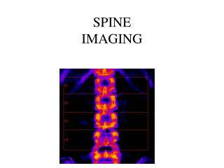
PA (AP) PROJECTION: SCOLIOSIS SERIES Pathology Demonstrated Degree and severity of scoliosis are shown. A scoliosis series frequently includes two AP (or PA) images taken for comparison—one erect and one recumbent.
Shielding Shield gonadal region without obscuring area of interest. Use breast shields for young females. Shadow shields placed on collimator may be used as shown in Fig. 10-46 and as evident in Fig. 10-48. Patient Position Position patient in the erect and recumbent position, with weight evenly distributed on both feet for the erect position. Part Position • Align midsagittal plane to CR and midline of IR, with arms at side. • Ensure no rotation of torso or pelvis if possible. (Scoliosis may result in twisting and rotation of vertebrae, making some rotation unavoidable.) • Place lower margin of IR a minimum of 1 to 2 inches (3 to 5 cm) below iliac crest (centering height determined by IR size and/or area of scoliosis).
Central Ray • CR perpendicular, directed to midpoint of IR • SID of 40 to 60 inches (100 to 150 cm); longer SID required with larger IR to obtain required collimation.
Respiration Suspend breathing on expiration. Notes: A PA rather than an AP projection is recommended because of the significantly reduced dose to radiation-sensitive areas, such as female breasts and the thyroid gland. Studies have shown that this projection results in approximately 90% reduction in dosage to the breasts. Scoliosis generally requires repeat examinations over several years for pediatric patients, with emphasis on the need for careful shielding.
ERECT LATERAL POSITION: SCOLIOSIS SERIES Structures Best Shown Spondylolisthesis, degree of kyphosis, or lordosis. Shielding Place contact shield or shadow shield over gonads without obscuring area of interest. Use breast shields for young females. Patient Position Position patient in erect lateral position with arms elevated, or, if unsteady, grasping a support in front. The convex side of the curve is positioned against the IR.
Part Position • Place pelvis and torso in as true a lateral position as possible. • Align midcoronal plane of body to CR and midline of IR. • Lower margin of IR should be a minimum of 1 to 2 inches (3 to 5 cm) below level of iliac crests (centering determined by IR size and patient size). Central Ray • CR perpendicular, directed to midpoint of IR • SID of 40 to 60 inches (100 to 150 cm); longer SID required with larger IR to obtain required collimation