Download
1 / 12
130 likes | 279 Vues
Signal to Noise+Interference (SNIR) Variations on multiple TVWS channels. Authors:. January15, 2013.

E N D
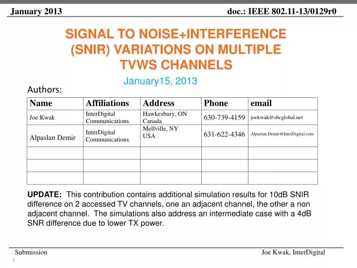
Signal to Noise+Interference (SNIR) Variations on multiple TVWS channels Authors: January15, 2013 UPDATE: This contribution contains additional simulation results for 10dB SNIR difference on 2 accessed TV channels, one an adjacent channel, the other a non adjacent channel. The simulations also address an intermediate case with a 4dB SNR difference due to lower TX power.
Simulation Overview • Main goal: • Compare 2 channel MAC layer throughputs using 2 cases: • MAC layer channel aggregation using one interleaver on each channel and independent MCS selection based on each channel SNIR • PHY layer bonding using a single interleaver for both channels and a common MCS on bonded channels (11af baseline) • Simulation assumptions • Rms Delay Spread: 100ns • Two-channel operation • Packet length • 1000 bytes for PHY bonding (Case B) over 2 channels • 500 bytes for MAC layer aggregation (Case A) on each channel • Same noise level on both channels • Different transmit power on two channels • P_Tx1 = 40mw (adjacent) P_Tx2 = 100mw (non-adjacent) • GI = 6 µs • Target PER: 10% --MCS adaptation threshold for BOTH cases
Consider Two Cases • Case A: MAC layer aggregation • Each channel has independent MCS • One interleaver on one channel • MCS selection on each channel follows Table 23-19 of 802.11af specs • Case B: 802.11af- PHY layer bonding • One interleaver over two channels • Same MCS for two aggregated channels • One encoder and same modulation modes • MCS selection on two aggregated channel follows Table 23-23 of 802.11af specs
Simulation Results - PER Performances of one channel(CaseA) Fig.1 PER vs. SNR for a single 6MHz TVWS channel
Simulation Results - PER Performances of two-bonded- channel (Case B) Fig.3 PER vs. (S1+S2)/2N0, where S1 and S2 are transmit power for channel 1 and channel 2 respectively, N0 is the noise level on each channel, transmit power on channel2 is 2.5 times of transmit power on channel1, i.e., S2 = 2.5S1 and interference on channel 1 is 5dB higher than the noise level and no interference on channel 2. Fig.2 PER vs. (S1+S2)/2N0, where S1 and S2 are transmit power for channel 1 and channel 2 respectively, N0 is the noise level on each channel, S2 = 2.5S1 (TxPower Difference on two channels = 4dB)
Simulation Results- Received SNIRs and MCS’s for 4dB Tx Power Difference
Simulation Results - Throughput Comparison between MAC layer aggregation and PHY bonding with single interleaver and a common MCS SNR difference between two channels = 4dB Case A Case B Fig.6 MAC layer throughput comparison between Independent MCS selection (MAC layer aggregation) and PHY layer bonding with single interleaver and a common MCS Fig.7 Throughput Gain of Independent MCS selection (MAC layer aggregation) over PHY layer bonding with a common MCS
Simulation Results- Received SNIRs and MCS’s for 4dB Tx Power Difference and 5dB Interference Difference for 10dB SNIR difference
Simulation Results - Throughput Comparison between MAC layer aggregation and PHY bonding with a single interleaver and a common MCS SNR difference between two channels = 10dB (TxPowDiff = 4dB, InterferenceDiff = 5dB) Case A Case B Fig.7 MAC layer throughput comparison between Independent MCS selection (MAC layer aggregation) and PHY layer bonding with single interleaver and a common MCS Fig.8 Throughput Gain of Independent MCS selection (MAC layer aggregation) over PHY layer bonding with a common MCS
Weak Channel Throughput Contribution in MAC Layer Aggregation (Case A)
Discussions • In the high SNR range, MAC layer aggregation provides slightly lower throughput than PHY layer bonding • The highest MCS is selected in both cases • Higher overhead ratio of two packets generated for one transmission in MAC layer aggregation than one packet generated for two bonded channels in the PHY layer bonding case • For higher SNIR difference and larger distance, the throughput gain of MAC layer aggregation becomes evident • Some gain drops at certain distances • Quantization error on MCS selection • PER curves of MCS2 and MCS3 are crossed over for the case that SNIR difference is 10dB (Fig.3) • Gain of MAC layer aggregation over PHY layer bonding
Summary • Highly variable SNIR levels on aggregated TVWS channels: • Different transmit power limits on adjacent/nonadjacent TVWS channels • High interference levels on on DTV adjacent channels from DTV adjacent channel emissions. • Single MCS utilization for bonded channels leads to significant degradation and waste of spectrum • Independent MCS for multichannel permits efficient use of resources in real TVWS environments. • TGaf draft requires use of single MCS for multichannel and should be modified to add an option to permit effective multichannel operation using independent MCS selection.