Download
1 / 24
240 likes | 344 Vues
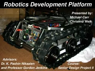
RP10 Robotics Platform. Team Cyberdyne Interim Presentation February 17, 2009, 4-5 PM. Project Sponsor: Dr. Wayne Walter, RIT KGCOE Faculty Coach: Dr. James Vallino. History of RP10 Platform. KGCOE Multidisciplinary Senior Design Preceding project: P08201 (20071-3)

E N D
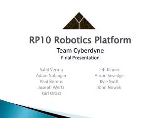
RP10 Robotics Platform Team Cyberdyne Interim Presentation February 17, 2009, 4-5 PM Project Sponsor: Dr. Wayne Walter, RIT KGCOE Faculty Coach: Dr. James Vallino
History of RP10 Platform • KGCOE Multidisciplinary Senior Design • Preceding project: P08201 (20071-3) • 2ND generation platform • Like “next model year” in auto industry • Built by EE, IE, ME students • Up to 4 motor modules • 10 kg payload • PC software for remote control
Project Synopsis Microsoft Robotics Developer Studio (MRDS) Model RP10 Simulation Platform Control Application Platform API .NET Other bindings . . . Wireless RF or Wired (Serial Cable) Motion commands, diagnostics RP10 Microcontroller (MCU) Motors Batteries Drive Platform Software Encoders Steer
Pictures of the MRDS Visual Programming Language 3-D Visualized Simulation
Process Methodology Choice • Spiral • Cycles with upfront risk-oriented evaluation • Iterative nature • Addresses significant uncertainty frequently • Cycles every 2-3 weeks • Obvious general risks early on • Inappropriate decisions due to inexperience • Hardware incapability against design • Platform instability • Resource unavailability (i.e., tools)
Schedule for 20082 Continued . . .
Metrics • Time tracking (up to week 9) • Hours estimated: 726.65 • Hours actual: 723.75 • Total hours for cycle 2: 284 (39%) • No other metrics tracked • Primarily product-oriented
Cycle 2 (C2) - Risks • Cannot create a comprehensive RP10 simulation in MRDS. • Communication between MCU and PC is unreliable. • Designs for MRDS implementation and platform API are incompatible. • Cannot use encoders to track angular wheel position.
C2 - Requirements Elicitation • Limitations of RP10 platform • P08201 documentation • Experimentation to fill in gaps • Interviews with KGCOE professors • Understand applications of platform • Influence API design • Discussions on simulation detail • Command set from API • Physical characteristics from Simulink
Notable Requirements • Platform • Control individual motors for drive, steer • Determine wheel angular position • Model • Build a 3D model of the RP10
C2 - Design Process • Platform • Split platform into subsystems • API • Communication Protocol • MCU • Divide sub-team across subsystem preferences • Collaborate to resolve interface issues • Model • Defined assets necessary for a simulation • Manifests, services, 3D model, etc. • Divided sub-team by expertise
Architecture - Platform .NET PC User Interface (GUI/CLI) Robot Control Commands (i.e., set speed, go, stop, etc.) Communication Manager Abstracts communication hardware (wireless or wired) Protocol over Serial Cable Responds to commands from PC, acknowledges commands Executable MCU* PWM* signals Motors *Microcontroller Unit, Pulse Width Modulation
Communication Protocol • Packets • Operation code (1 byte) • Data (optional 1 byte) • Acknowledges each byte received • Heartbeats from PC • Automatic robot shutdown if no beat received • Command error checking on PC
SolidWorks • Create a 3-D model to import into MRDS • Includes material properties • 2008 vs. 2009 • Collada Export in 2009 • Licensing • Future Plans
Notable Trade-offs • PC vs. MCU functionality • PC: Easier to modify software • MCU: Software closest to hardware • Modeling a wheel vs. entire drive train • Wheel: Simplifies model development • Drive train: More accurate with all gears
Implementation Technologies • Platform • FreeScale MCU with CodeWarrior IDE • Hardware specific registers • C programming • C#.NET with Visual Studio • PC control software • Model • Visual Programming Language (VPL) with MRDS • Drag-drop programming of objects and actions • C#.NET • Interface with low-level MRDS components, API
Test Strategy & Issues • Platform • Manual acceptance tests through PC control • Coverage of all commands in protocol • Physical observation of correctness (i.e., yardstick) • Reliability, performance testing • Model • Simulated part function unit tests • Simulation test course for long duration • Dashboard control in simulated environment • Comparison of part functions between simulation and real robot
C2 - Results • Platform • Designs for API, communication protocol • Requirements document • PC-MCU prototype of protocol • Model • Initial overall platform characteristics • SolidWorks motor module, frame models • Requirements, test strategy documents
Lessons • Learn and abide by the methodology • Set specific goals and work to them • Plan activities separate of needed tools • Do not isolate sub-teams