Download
1 / 21
220 likes | 381 Vues
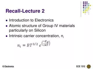
Recall-Lecture 3 . Current generated due to two main factors Drift – movement of carriers due to the existence of electric field Diffusion – movement of carriers due to gradient in concentrations. Recall-Lecture 3 . Introduction of PN junction Space charge region/depletion region

E N D
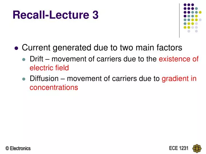
Recall-Lecture 3 • Current generated due to two main factors • Drift – movement of carriers due to the existence of electric field • Diffusion – movement of carriers due to gradient in concentrations
Recall-Lecture 3 • Introduction of PN junction • Space charge region/depletion region • Built-in potential voltage Vbi • Reversed biased pn junction • no current flow • Forward biased pn junction • current flow due to diffusion of carriers. Vbi
CIRCUIT REPRESENTATION OF DIODE i vD The I -V characteristics of the ideal diode. Reverse bias Conducting state V = 0V Reverse biased open circuit Conducting state short circuit
CIRCUIT REPRESENTATION OF DIODE – Piecewise Linear Model i vD Represented as a battery of voltage = V = V Reverse bias Conducting state Reverse biased open circuit V VD =V for diode to turn on. Hence during conducting state:
i vD Represented as a battery of voltage = V and forward resistance, rfin series + VD - = rf V CIRCUIT REPRESENTATION OF DIODE – Piecewise Linear Model Reverse bias Conducting state Reverse biased open circuit V VD ≥V for diode to turn on. Hence during conducting state:
Diode Circuits: DC Analysis and Models Example Consider a circuit with a dc voltage VPSapplied across a resistor and a diode. Applying KVL, we can write, or, The diode voltage VD and current ID are related by the ideal diode equation: (IS is assumed to be known for a particular diode) Equation contains only one unknown, VD:
Diode Circuits: Direct Approach Question Determine the diode voltage and current for the circuit. Consider IS = 10-13 A. and ITERATION METHOD
Diode Circuits: Using Models Example Determine the diode voltage and current using a piecewise linear model. Assume piecewise linear diode parameters of Vf = 0.6 V and rf = 10 Ω. Solution: The diode current is determined by:
DIODE DC ANALYSIS I • Find I and VOfor the circuit shown below if the diode cut in voltage is V = 0.7V + VO - I = 0.2325mA Vo = -0.35V
Find I and VOfor the circuit shown below if the diode cut in voltage is V = 0.7V I + VO - I = 0.372mA Vo = 0.14V
Example 2 Determine ID if V = 0.7V R = 4k b)If VPS = 8V, what must be the value of R to get ID equal to part (a)
Sinusoidal Analysis The total input voltage vI = dcVPS + acvi iD= IDQ + id vD = VDQ+ vd IDQ and VDQ are the DC diode current and voltage respectively.
If vd << VT, the equation can be expanded into linear series as: The DC diode current Is: Diode Circuits: AC Equivalent Circuit • Current-voltage Relation The relation between the diode current and voltage can be written as: VDQ = dc quiescent voltage vd = ac component The -1 term in the equation is neglected. The equation can be written as:
iD = ID [ 1 + vd/VT] iD = ID + ID vd / VT = ID + id where id =ID vd / VT using Ohm’s law: I = V/R hence, id = vd / rd compare with id =ID vd / VT which reveals that rd = VT / ID CONCLUSION: During AC analysis the diode is equivalent to a resistor, rd
VDQ = V rd IDQ id DC equivalent AC equivalent
VDQ = V IDQ Example 1 Analyze the circuit (by determining VO & vo ). Assume circuit and diode parameters of VPS = 5 V, R = 5 kΩ, Vγ = 0.6 V & vi = 0.1 sin ωt
rd id
EXAMPLE 2 • Assume the circuit and diode parameters for the circuit below are VPS = 10V, R = 20k, V = 0.7V, and vi = 0.2 sin t. Determine the quiescent current, IDQ and the time varying current.