Download
1 / 20
230 likes | 466 Vues
TSM 363 Fluid Power Systems. Electronic Controls in Hydraulics Systems. Automated Functions – A Technical Trend. E/H Systems (Conventional Design). M. Controller. M. E/H Systems (Programmable Design). M. Controller. M. Basic Electrical Devices.

E N D
TSM 363 Fluid Power Systems Electronic Controls in Hydraulics Systems
E/H Systems (Conventional Design) M Controller M
E/H Systems (Programmable Design) M Controller M
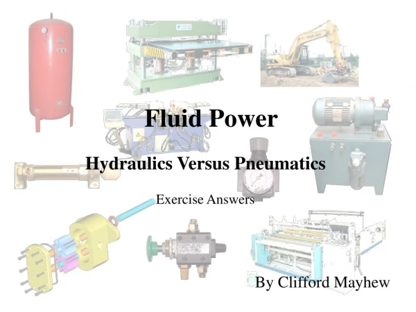
Basic Electrical Devices Seven devices commonly used in the control of electrohydraulic systems: • Push-button switches • Limit switches • Pressure switches • Drivers (Servo or Solenoids) • Relays • Timers • Temperature switches
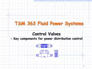
Operator control Input Signal time Valve control E/H Control Valves • On/Off solenoid • Proportional Solenoid • Low cost • PWM control of the solenoid • Advanced controls • Servo Valves • Torque motors • Costly, limited applications
1. Traditional air-gap type proportional solenoid driver 2. Wet-armature type proportional solenoid driver Commonly Used Proportional Solenoid Drivers
Va Vs Solenoid Characteristics of PWM Signals • Amplifier acts as a variable resistance to power solenoid • Voltage fully-on • Amplifier has zero resistance, no heat build-up • Maximum voltage to solenoid • Voltage fully-off • No power to amplifier, no heat buildup • High pulse-rate signal of full-on/full-off • Pulse rate is faster than the solenoid can react • Solenoid sees these as an average voltage
Option 3: Servo E/H Valve • Servo mechanism • Electric motor • Position feedback potentiometer • Reduction gear • Actuator arm
Output Input E/H Valve Actuator Open Loop Control Circuits • Simple circuit with no measurement of the performance at various settings
Closed-Loop Control • Feedback enhances performance • Dynamic response and stability reference command + System dynamics output Controller - feedback
Properties of Valve Response: Stability Response Time
Lecture Summary • Discussed the basic principles of electro-mechanical drivers for E/H valves: • Solenoid driver • Servo driver • Introduced a few key parameters describing the performance of an E/H valve: • Deadband • Saturation • Hysteresis