Download
1 / 43
430 likes | 558 Vues
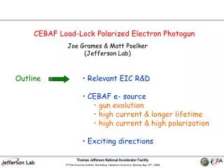
Polarized Electron Sources. Joe Grames, and many others…. Source Group Members - Phil Adderley, Maud Baylac, Joshua Brittian, Daniel Charles, Jim Clark, Joe Grames, John Hansknecht, Ken Law, Matt Poelker, Marcy Stutzman

E N D
Polarized Electron Sources Joe Grames, and many others… Source Group Members - Phil Adderley, Maud Baylac, Joshua Brittian, Daniel Charles, Jim Clark, Joe Grames, John Hansknecht, Ken Law, Matt Poelker, Marcy Stutzman Source Group Hall of Famers - Charlie Sinclair, Bruce Dunham, Larry Cardman, Scott Price, Peter Hartmann, Michael Steigerwald, Tony Day, Kim Ryan, Danny Machie, John Hogan, Bill Schneider, Reza Kazimi, Paul Rutt, Ganapati Rao Myneni JLAB GSA Pizza Seminar September 15, 2004
A history 30 years and growing… Polarized electron beams have wide application in studies which range from materials science to nuclear and high energy physics: the latter has driven the development of polarized e- sources Semiconductor sources introduced in 1975 via optical pumping of GaAs First e- source on an accelerator (P ~ 35%) : PEGGY, at SLAC (1978) Strained GaAs reaches higher polarization (P~75%) in early 90’s (SLAC) Nowadays, many accelerator facilities have used GaAs sources: SLAC, MAMI, ELSA, CEBAF, MIT-BATES Relatively new => Unpolarized electrons for Light Sources and development for high current (10’s mA) polarized beams.
Optical pumping between P and S 1/2 3/2 - + m J 3-1 P = = +/- 50% S P P 3+1 e E < E < E 3/2 1/2 1/2 gap+ gap Optical Pumping of GaAs = 1.42 eV =0.34 eV hc / l
Bare GaAs surface; Large work function. No electrons Alkalai (Cs) reduces work function. Some electrons. Cesium + Oxidant (O or NF3) “Negative Electron Affinity”. Many electrons E > 0 E < 0 E 0 a a a Photoemission from GaAs
P = 3-1 3+1 = 50% The First GaAs Photoemission Gun
First High Voltage GaAs Photogun I ~ 1 mA to Electrons into the accelerator Dec., 1977 Collaboration announces parity violation June, 1978
Split degeneracy of P & optical pumping between P and S 3/2 1/2 3/2 + - P = +/- 100%, with E < E < E e Optical Pumping of strained GaAs gap+ gap
split degeneracy of P 0.1 μm x=0.29 3/2 250 μm 250 μm p-type GaAs substrate GaAs GaAs P P x x 1-x 1-x 600 μm Strained layer GaAs photocathode Bandwidth Semiconductor (formerly SPIRE) Strained GaAs • MOCVD-grown epitaxial spin-polarizer wafer • Lattice mismatch 0<x<0.29
Photocathodes 3” wafer cleaved into square photocathodes (15.5 mm) for mounting on a “stalk” using In and Ta cup.
Present JLab polarized gun design Ceramic Insulator Cathode (GaAs) Anode -100 kV Laser - e Cs NF 3 NEG coated beampipe Non evaporable getter pumps (NEG) 4,000 liter/s pump speed 5E-12 Torr
Gun Issues (Yesterday, Today & Tomorrow) • Lifetime at High Current (vacuum issues) • Adequate photocathode QE and polarization • Adequate Laser Power with RF pulse structure • Control of Helicity Correlated Systematics • Beam handling (space charge induced emittance growth)
0.6 GeV linac (20 cryomodules) 1497 MHz 67 MeV injector A B C (2 1/4 cryomodules) 1497 MHz RF separators Gain switched B 499 MHz diode lasers A 499 MHz, Df = 120 B C A C Pockels cell Gun Double sided septum Continuous Electron Beam Accelerator Facility
A B CA B C 1497 MHz 60 degrees • Use pulsed light to extract electrons only when we need them. • This prolongs operating lifetime of the gun. Synchronous Photoinjection
RF Gain Switching 0.5 GHz Diode seed laser 1 GHz 1.5 GHz Diode amplifier 2 GHz Lasers at CEBAF
Synchronous Photoinjection Chopper viewer for three beams; • Pulsed lasers and prebuncher ON • Pulsed lasers, prebuncher OFF • DC laser Beam to Hall B Beam to Hall A Beam to Hall C
…and photocathode lifetime Imperfect vacuum => QE degrades via ion backbombardment
Lifetime vs. Beam Location 2.4 mm off axis 1.6 mm off axis 0.8 mm off axis Center Ionized gas is attracted toward the electrostatic center of photocathode Solution => position laser spot (e- beam location) off axis
Limiting Active Area via Anodization Electrons emitted from edge of wafer hit vacuum chamber walls. This is bad for vacuum. Anodization eliminates inadvertent photoemission from locations not intentionally illuminated with laser light. 5 mm dia. Anodize photocathode in electrolytic bath of weak phosporic acid. 15 mm Photocathode “out of box”
Anodized vs. Unanodized Location #1; center 5mm (red) anodized Location #2; 0.8 mm off axis 11 mm (green) unanodized Location #3; 1.6 mm off axis
Better Vacuum = Longer Lifetime ~2.5E-11 Torr ~5.0E-11 Torr >15.0E-11 Torr
Gun Lifetime at CEBAF Gun charge lifetime degrading with time. Limited NEG pump lifetime/capacity?
Improve QE => Atomic Hydrogen Cleaning Photocathode sits here, inside vacuum chamber Molecular hydrogen dissociated with RF inductive discharge
Atomic Hydrogen Cleaning – bulk GaAs Extremely high QE from bulk GaAs Reliable cleaning method; No wet chemicals In situ cleaning
Hydrogen Cleaning – strained GaAs Polarization wo/ Hydrogen cleaning Polarization w/ Hydrogen cleaning Wavelength (nm)
Quantum Efficiency 0.2 % at 840 nm yields 1 mA/mW 1.0 % at 780 nm yields 6 mA/mW Polarization P ~ 75 % at 840 nm P ~ 35 % at 780 nm 2 e FOM I P e Diode lasers ~ 40 mW QE & polarization (strained GaAs)
High(er) Power Lasers Homemade Ti-Sapphire laser for GEp and GEn
Time-Bandwidth Ti:Sap • Passively mode-locked (SESAM) • Very reliable • (turn-key) • High power • (300+ mW) • Wavelength tunable • (peak polarization) • RF repetition rates • G0 ~ 31.1875 MHz • HAPPEX ~ 499 MHz
Laser Table ~ January `04 We rearrange the lasers every ~ three months
-3 Be doping (cm ) 19 18 17 5.10 5.10 5.10 GaAs (5 nm) GaAsP (3 nm) 14 pairs GaAs (4 nm) (2.5 μm) GaAs P 0.36 0.64 , 0<x<0.36 (2.5 μm) GaAs P 1-x x p-type GaAs substrate What’s new? Strained Superlattice GaAs SVT associates, per SLAC specs.
Higher Quantum Efficiency QE (%) QE ~ 1% versus 0.2% from “traditional” strained layer material we operate here Wavelength (nm)
Higher Beam polarization Measurements at Test Cave as high as 85% Accelerator measurement comparable Typical polarization from traditional material ~75% Polarization (%) Wavelength for Good QE and Polarization Wavelength (nm)
What about the gun horizon? Best Technology Load Lock Polarized Electron Gun High voltage Preparation Of NEA surface Load, heat and hydrogen clean
JLab FEL program with unpolarized beam ELIC with circulator ring Ave. Beam Current (mA) First low polarization, then high polarization at CEBAF Year First polarized beam from GaAs photogun Continuing Trend Towards Higher Average Beam Current