Download

1 / 24
240 likes | 342 Vues
Software Design. Mr. Manoj Kumar Kar. Basic Components of Software Design:.

E N D
Software Design Mr. Manoj Kumar Kar
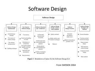
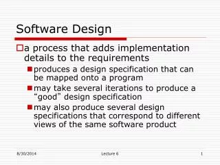
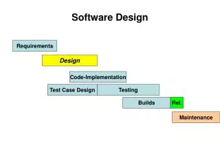
Basic Components of Software Design: • Software design deals with transforming the customer requirements, as described in the SRS document, into a form (a set of documents) that is suitable for implementation in a programming language. • Design activities can be broadly classified into two important parts: • Preliminary or high level design: • High level design tend to vary considerably from one methodology to another. High-level design means identification of different modules and the control relationships among them and the definition of the interfaces among these modules. • The outcome of high-level design is called the program structure or software architecture. • High level design can be represented in tree-like diagram called the structure chart to represent the control hierarchy in a high-level design. 2. Detailed design: • The outcome of the detailed design stage is usually known as the module-specification document.
Difference between analysis and design • The aim of analysis is to understand the problem with a view to eliminate any deficiencies in the requirement specification such as incompleteness, inconsistencies, etc. • The aim of design is to produce a model that will provide a seamless transition to the coding phase, i.e. once the requirements are analyzed and found to be satisfactory, a design model is created which can be easily implemented.
Items developed during the software design phase • For a design to be easily implemented in a conventional programming language, the following items must be designed during the design phase. • Different modules required to implement the design solution. • Control relationship among the identified modules. The relationship is also known as the call relationship or invocation relationship among modules. • Interface among different modules. The interface among different modules identifies the exact data items exchanged among the modules. • Data structures of the individual modules. • Algorithms required to implement each individual module.
Characteristics of a good software design • Correctness: A good design should correctly implement all the functionalities identified in the SRS document. • Understandability: A good design is easily understandable. • Efficiency: It should be efficient. • Maintainability: It should be easily amenable to change.
Features of a design document • In order to facilitate understandability, the design should have the following features: • It should use consistent and meaningful names for various design components. • The design should be modular. The term modularity means that it should use a cleanly decomposed set of modules. • It should neatly arrange the modules in a hierarchy, e.g. in a tree-like diagram.
Cohesion • Cohesion is a measure of functional strength of a module. A module having high cohesion and low coupling is said to be functionally independent of other modules. • The term functional independence means that a cohesive module performs a single task or function. A functionally independent module has minimal interaction with other modules.
Classification of cohesion Coincidental Cohesion: • A module is said to have coincidental cohesion, if it performs a set of tasks that relate to each other very loosely, if at all. • In this case a module contains a random collection of functions. • It is likely that the function has been put in the module out of pure coincidence without any thought or design.
Classification of cohesion continues Logical cohesion: • A module is said to be logically cohesive, if all elements of the module perform similar operations. Temporal cohesion: • When a module contains functions that are related by the fact that all the functions must be executed in the same time span, the module is said to exhibit temporal cohesion. • The set of functions responsible for initialization, start-up, shutdown of some process, etc. exhibit temporal cohesion.
Classification of cohesion continues Procedural cohesion: • A module is said to possess procedural cohesion, if the set of functions of the module are all part of a procedure (algorithm) in which certain sequence of steps have to be carried out for achieving an objective, e.g. the algorithm for decoding a message. Communicational cohesion: • A module is said to have communicational cohesion, if all functions of the module refer to or update the same data structure, e.g. the set of functions defined on an array or a stack. Sequential cohesion: • A module is said to possess sequential cohesion, if the elements of a module form the parts of sequence, where the output from one element of the sequence is input to the next. • For example, in a TPS, the get-input, validate-input, sort-input functions are grouped into one module.
Classification of cohesion continues Functional cohesion: • Functional cohesion is said to exist, if different elements of a module cooperate to achieve a single function.
Coupling • Coupling between two modules is a measure of the degree of interdependence or interaction between the two modules. • If two modules interchange large amounts of data, then they are highly independent. • The degree of coupling between two modules depends on their interface complexity. • The interface complexity is basically determined by the number types of parameters that are interchanged while invoking the functions of the module. • A module having high cohesion and low coupling is said to be functionally independent of other module.
Classification of Coupling Data coupling: • Two modules are data coupled, if they communicate through a parameter. • An example is an elementary data item passed as a parameter between two modules, e.g. an integer, a float, a character, etc. • This data item should be problem related and not used for the control purpose. Stamp coupling: • Two modules are stamp coupled, if they communicate using a composite data item such as a record in PASCAL or a structure in C.
Classification of Coupling continues Control coupling: • Control coupling exists between two modules, if data from one module is used to direct the order of instructions execution in another. • An example of control coupling is a flag set in one module and tested in another module. Common coupling: • Two modules are common coupled, if they share data through some global data items. Content coupling: • Content coupling exists between two modules, if they share code, e.g. a branch from one module into another module.
Functional independence • A module having high cohesion and low coupling is said to be functionally independent of other modules. • By the term functional independence, we mean that a cohesive module performs a single task or function. A functionally independent module has minimal interaction with other modules.
Need for functional independence • Functional independence is a key to any good design due to the following reasons: Error isolation: • Functional independence reduces error propagation. The reason behind this is that if a module is functionally independent, its degree of interaction with the other modules is less. Therefore, any error existing in a module would not directly effect the other modules. Scope of reuse: • Reuse of a module becomes possible. Because each module does some well-defined and precise function, and the interaction of the module with the other modules is simple and minimal. Therefore, a cohesive module can be easily taken out and reused in a different program. Understandability: • Complexity of the design is reduced, because different modules can be understood in isolation as modules are more or less independent of each other.
Function oriented Software design Structured Analysis: • Structured analysis is used to carry out the top-down decomposition of a set of high-level functions depicted in the problem description and to represent them graphically. • During structured analysis, functional decomposition of the system is achieved. That is, each function that the system performs is analyzed and hierarchically decomposed into more detailed functions. • Structured analysis technique is based on the following essential underlying principles: • Top-down decomposition approach. • Divide and conquer principle. • Graphical representation of the analysis results using Data Flow Diagrams
Data Flow Diagram (DFD) • The DFD (also known as a bubble chart) is a hierarchical graphical model of a system that shows the different processing activities or functions that the system performs and the data interchange among these functions. • Each function is considered as a processing station (or process) that consumes some input data and produces some output data. • The system is represented in terms of the input data to the system, various processing carried out on these data, and the output data generated by the system. • A DFD model uses a very limited number of primitive symbols to represent the functions performed by a system and the data flow among these functions.
Importance of DFDs in a good software design • The basic needs of DFD are mentioned as below • DFD is a very simple formalism. • It is simple to understand and use. • Starting with a set of high-level functions that a system performs, a DFD model hierarchically represents various sub-functions.
Data dictionary • A data dictionary lists all data items appearing in the DFD model of a system. • The data items listed include all data flows and the contents of all data stores appearing on the DFDs in the DFD model of a system. • A data dictionary lists the purpose of all data items and the definition of all composite data items in terms of their component data items. • For the smallest units of data items, the data dictionary lists their name and their type.
Data dictionary continued • Composite data items can be defined in terms of primitive data items using the following data definition operators: +: Denotes composition of two data items, e.g. a+brepresents data a and b. [,,]: Represents selection, i.e. any one of the data items listed in the brackets can occur. For example, [a,b] represents either a occurs or b occurs. (): The contents inside the bracket represent optional data which may or may not appear. e.g. a+(b) represents either a occurs or a+boccurs. {}: Represents iterative data definition, e.g. {name}5 represents five name data. {name}* represents zero or more instances of name data. =:Represents equivalence, e.g. a=b+cmeans that a represents b and c. /* */: Anything appearing within /* and */ is considered as a comment.
Importance of data dictionary • A data dictionary plays a very important role in any software development process because of the following reasons: • A data dictionary provides a standard terminology for all relevant data for use by the engineers working in a project. A consistent vocabulary for data items is very important, since in large projects different engineers of the project have a tendency to use different terms to refer to the same data, which unnecessary causes confusion. 2. The data dictionary provides the analyst with a means to determine the definition of different data structures in terms of their component elements.