Download

1 / 30
300 likes | 577 Vues
Electromagnetic Induction. What’s Next?. Electromagnetic Induction Faraday’s Discovery Electromotive Force Magnetic Flux Electric Generators Lenz’s Law Self-Inductance Transformers. What do we know?. Hans Christian Oersted showed that moving charges create a magnetic field.

E N D
What’s Next? • Electromagnetic Induction • Faraday’s Discovery • Electromotive Force • Magnetic Flux • Electric Generators • Lenz’s Law • Self-Inductance • Transformers
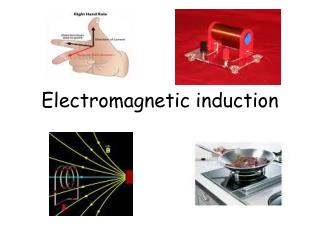
What do we know? • Hans Christian Oersted showed that moving charges create a magnetic field.
Faraday’s Hypothesis • If moving charges produced a magnetic field, could a moving or changing magnetic field produce a current?
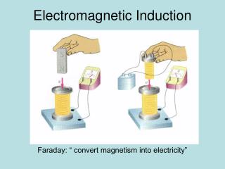
Faraday’s Discovery • Faraday discovered that he could induce current by moving a wire loop through a magnetic field or moving the magnetic field through a wire loop. • Faraday’s Discovery is known as Electromagnetic Induction • Faraday's Discovery
x x x x x x x x x x x x x x x x x x x x x x x x x x x + - L v F Electromotive Force • Last week we learned the Lorentz Force. FB = qvB sinθ = ILB • When a conductor moves through a magnetic field, a force is exerted on these charges causing them to separate, inducing an EMF.
Electromotive Force • We know: W = Fd and V = W/q. V = Fd/q Using algebra and solving for F: F = Vq/d F = qvB Set these two relationships equal to one another and then solve for V, which will now be represented as EMF: EMF (V) = vBL Where: L is the length of a conductor passing through a magnetic field. EMF = Electromotive Force (Volts)
I + x x x x x x x x x x x x x x x x x x x x x x x x x x x x x x x x x x x x I F v - Electromotive Force • The EMF results when the conductor has a velocity component perpendicular to the magnetic field. • Use RHR #1 where the thumb points in the direction of the velocity. The force on the bar is opposite the velocity. I
Example 1: EM Induction A segment of a wire loop is moving downward through the poles of a magnet, as shown. What is the direction of the induced current? a. The current direction is out-of the page to the left. b. There is no induced current. c. The current direction is into the page to the right.
Example 2: EM Induction • The drawing shows three identical rods (A, B, and C) moving in different planes in a constant magnetic field directed along the +y axis. The length of each rod and the speeds are the same, vA = vB = vC. Which end (1 or 2) of each rod is positive? • Rod A: • 1 b. 2 c. neither • Rod B: • 1 b. 2 c. neither • Rod C: • 1 b. 2 c. neither
Electromagnetic Induction • Why is it important? • Motors • Generators • Transformers
Electric Generators • Invented by Michael Faraday. • Convert mechanical energy into electrical energy. • Similar to an electric motor, but function in an opposite manner. • Electrical power generation is the foundation by which electricity is supplied to homes and businesses around the world. • Electricity is generated in many ways - hydroelectric, nuclear, coal, gas, oil fired, wind solar, geothermal.
Magnetic Flux What is magnetic flux? • Like electric flux • A measure of the strength of the magnetic field, B, passing through a surface perpendicular to the field. • For a bar magnet, the flux is maximum at the poles. • The more magnetic field lines, the higher the flux. =BAcos
Magnetic Flux and EMF • We already know: EMF = vBL • v = Δx/Δt = (x – xo) (t – to) • EMF = (Δx/Δt)BL = (xL – xoL) B = (BA) – (BAo) (t – to) (t – to) EMF = -ΔΦ/Δt Where: Φ = BA cos and • = the angle the normal to the surface makes with B (in this drawing it is 0o). I + x x x x x x x x x x x x x x x x x x x x x x x x F I v -
Faraday’s Law of EM Induction • In the drawing on the previous slide, there is only one loop in the circuit. • When there is more than one loop in a circuit, as in the coil of a solenoid, the EMF induced by a changing magnetic field will increase by a factor equal to the number of loops in the coil. EMF = -N ΔΦ/Δt Where N = the number of loops in the coil. • Note: The units for Φ are Webers (Wb) or 1 Tm2
I • x • x x • Magnetic Flux & Generators Direction of Rotation v v v w B v v v Zero Current Min Change in Flux Max Current Max Change in Flux Axis of Rotation
Magnetic Flux & Generators • When the armature is at 90o with the magnetic field, the current will be zero because the rate of change in magnetic flux through the coil will be at a minimum. • When the windings of the armature are aligned with the direction of the magnetic field, the current will be at a maximum because the rate of change in magnetic flux will be at a maximum.
Principle Operation and Characteristics of a Generator • The armature turns such that the coils of wire cut through the magnetic field inducing an EMF in the coil. • The magnetic field or the conductor need to be moving in order for an EMF to be generated. • The greater the change in magnetic field, the greater the EMF, ie. the faster the armature turns, the greater the power produced. • Use RHR #1 to determine the direction of current through the coil. • Generator
Lenz’s Law • The induced EMF resulting from a changing magnetic flux has a polarity that leads to an induced current whose direction is such that the induced magnetic field opposes the original flux change. • If the magnetic field is increasing, a current will develop to oppose the increasing magnetic field. • If the magnetic field is decreasing, a current will develop to create a magnetic field in the same direction as the one that is decreasing. • A current will form that attempts to keep the magnetic field constant. • Lenz’s Law abides by the laws of conservation of energy.
Lenz’s Law Lenz's Law
No Current Induced Current x x x x x x x x x x x x x x x x x x x x x x x x No Current Induced Current No Current Lenz’s Law Current will be induced in the copper ring when it passes through a region where the magnetic field changes. When the magnetic field is constant or absent, their will be no induced current.
Applications of Lenz’s Law (Eddy Currents) • Eddy current balances. • Eddy current dynamometer. • Metal detectors (Lenz's Law) • Braking systems on trains. • What are Eddy currents? • Eddy currents are currents created in conductors to oppose the changing magnetic fields they are exposed to. • Eddy currents respond to the changes in an external magnetic field. • Eddy currents can form in conductors even if they are not capable of being magnetized.
Lenz’s Law and Motors – Back EMF • When a current carrying wire moves in a magnetic field, an EMF is produced called the back EMF. • The back EMF opposes the current in the motor resulting in a decrease in the total current through the motor. • As the motor slows down, the current will increase. • Back EMF’s may cause sparks at outlets and switches when circuits are disconnected while in use.
Back EMF in Electric Motors • Both motors and generators consist of coils that rotate in a magnetic field. • There are two sources of EMF: • An applied EMF to drive the motor. • An EMF induced (back EMF) by the generator like action of the coil that opposes the applied EMF. EMFnet = Vapplied – EMFinduced I = (Vapplied – EMFinduced)/R
Self-Inductance • An increasing current in a coil will induce an EMF that is opposing to the current in the coil. NΦ = LI Where L is a constant called self-inductance. Substituting into Faraday’s Law of induction: EMF = -L ΔI/Δt Note: the negative sign shows that the EMF is always opposing the change in current. Note: the faster the change in current, the greater the EMF.
Transformers • Transformers are used to increase or decrease AC voltage. • Transformers that increase voltage are called step-up transformers. • Transformers that decrease voltage are called step-down transformers. • Transformers efficiently change voltages with little loss of energy.
Transformer Design • Transformers consist of two windings wrapped around an iron core. • The iron core is easily magnetized and will enhance the magnetic field. • Mutual Inductance: The changing current in one coil (primary) will induce an EMF in the other coil (secondary).
Power losses are minimal for transformers Transformers (cont.) • The EMF induced (secondary voltage, Vs) in a secondary coil is proportional to the primary voltage (Vp). • The EMF induced is also proportional to the number of windings (Ns) in the secondary coil. • The EMF is inversely proportional to the number of windings in the primary coil (Np). Vs/Vp = Ns/Np Pp = Ps VpIp = VsIs Rearranging: Is/Ip = Vp/Vs = Np/Ns
Key Ideas • Electromagnetic induction: is the process by which current is generated by moving a conductor through a magnetic field or a magnetic field through a conductor. • The induced current is maximum when the relative motion of the conductor is perpendicular to the magnetic field. • The induced voltage is called EMF (=vBL). • Magnetic flux is a measure of the strength of the magnetic field passing through a surface. • A generator is a device that converts mechanical energy into electrical energy. • Generators are similar to motors.
Key Ideas • Lenz’s Law: The induced EMF resulting from a changing magnetic flux has a polarity that leads to an induced current whose direction is such that the induced magnetic field opposes the original flux change. • Self-Inductance: A changing current in a coil will induce an EMF that opposes the change in current. • Transformers convert high voltage/low current electrical energy to low voltage/high current electrical energy. • Transformers consist of two coils (primary and secondary) wrapped around a common iron core.