Download
1 / 25
250 likes | 320 Vues
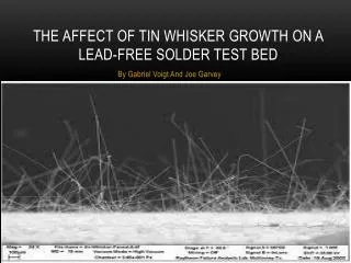
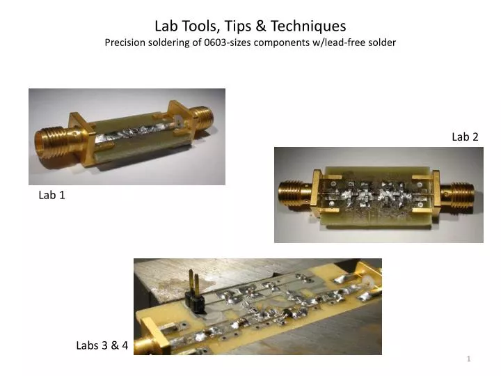
Lab Tools, Tips & Techniques P recision s oldering of 0603-sizes components w/lead-free solder. Lab 2. Lab 1. Labs 3 & 4 .

E N D
Lab Tools, Tips & Techniques Precision soldering of 0603-sizes components w/lead-free solder Lab 2 Lab 1 Labs 3 & 4
When you go into the Electronics lab and start to solder components onto a printed circuit board, you’ve really entered into a world of Chemisty. Solder is amazing. Billions of dollars and man-hours have gone into the engineering that has created the solder eco-system. If you have friends in the Materials Science department or the MechE department, you can tell them that you just went to lab and did Metallurgy and Heat Transfer. When you solder something, you’re essentially trying to make a connector. If your circuit doesn’t work, it’s usually a connector problem. Take the time to make good solder connections - and you will save eons of debugging time later.
A few years ago, solder contained lead (and tin). Lead is now forbidden due to certain laws. (RoHS – Reduction of Hazardous Substances. You can look it up on wikipedia.) Solder without lead is called no-lead solder, or lead-free solder. It’s mostly tin, with some silver and copper. All resistors, capacitors, inductors, chips, etc. these days come in packages where the leads are plated with no-lead solder. Consequently, you should specify any printed circuit boards you make, that they should be plated also with lead-free solder. And when you assemble components onto your boards you should use lead-free solder. The printed circuit board industry has engineered these solder plating materials to work together, and they don’t work as well when you mix leaded solder with lead-free solder. Flux is the magic ingredient that really makes the system work. Flux is a corrosive liquid (sometimes a paste) that helps to scrub away oxides and clean the surfaces of components and boards so that they can stick together when heat is applied. Surfaces can only stick when they are clean and free of oxides. Lead-free solder requires more heat (at 20 oC higher temperatures) than the old leaded solders. To get heat to transfer from a soldering iron to your board-component interface, you need time (patience), flux, ... and a steady hand. A flux pen is a dispenser of flux. If it’s been sitting around, its tip is probably dry. You have to push down on the tip a few times to prime it. Try it on a piece of paper to make sure the liquid comes out the tip.
When you send a printed circuit board design to a board house for fabrication, you can order different types of solder plating (plating on top of the copper). Both pictures below are of lead-free solder plating, but the one on the left is an electro-less plating called Immersion Tin. It’s very thin (~ 35 microinches, 0.9 um) and hard to solder to. Immersion Tin is meant for assembly houses which apply solder paste using a stencil and then put the components on the paste and send the board through a conveyor oven. The picture on the right is a board that has been dipped in a pot of molten lead-freesolder in a process called HASL (hot-air solder-leveled). As the board is pulled out of the bath, it passes through two knife-edged vents of hot air which blow the molten solder off so that the plating is level and even. This adds about half a mil to your copper (0.0005”, or 0.0127 mm or 12.7 um). This type of plating works much better for hand soldering of components. If you find an old board in a lab, how do you know if it has been plated with leaded solder vs. lead-free solder? Easy, just pour a little nitric acid in a beaker and drop the board in. Nitric acid attacks tin. Since lead-free solder is mostly tin, if your beaker reacts vigorously, then your board was plated with lead-free solder.
Lab 3 amplifier board with immersion tin plating BJT for Lab 3 On HASL-plated boards, the plating is thick enough that you can place a component like this on a trace and (after applying flux), you can hold a hot blunt-tipped soldering iron on the BJT’s lead and solder the chip to the board w/o adding any extra solder. That is, there’s already enough solder on the chip’s leads and on the board (and if both types of solder plating are lead-free, and you use the correct flux), that they will stick together. You can’t do that on an immersion tin plated board; the plating is too thin. Lead-free HASL plating
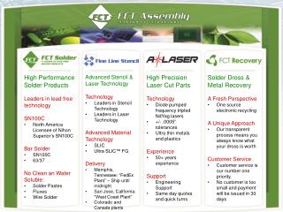
When you go into the lab, take the time to look closely at the materials you’ll be using. Pick up a roll of solder, look for the part number and manufacturer, then go to their web site and look for a datasheet. Ours is actually marked as lead-free solder. It’s 96.5% tin, 3% silver and 0.5% copper. Part # http://www.kester.com/Portals/0/documents/Electronic-Assembly-Materials.pdf From the datasheet for formula 48 activated rosin solder:
Do the same for the flux pens in the lab. If you look up this Kester 951 flux, you’ll find it’s for the old leaded solders. Don’t use this. What you want for lead-free boards is this 959T flux: http://www.kester.com/SideMenu/Products/WaveSolderingMaterials/Fluxes.aspx
Also take a close look at the soldering tips in the lab. Do you think you can get much heat transfer with these pointy geometries? They’re also dirty and oxidized, which will further inhibit heat transfer. You’ll get better heat transfer if you have more surface area at the tips. Metcal SSC-7xxseries tips (hot for lead-free) for their SP200 soldering system. Available from All-Spec.com. Bevel tip SSC-747A Chisel tip SSC-736A
“Clean” the tip by applying flux, then melting some solder right on the tip, then rub it off in the gold brillo. Repeat a few times. Bevel tip Chisel tip It should end up looking tinned like this.
Sanity Check A simple test is to melt a length of solder off the roll. If your iron can’t do this simple task, go back and keep cleaning and tinning. If the tip is so old, oxidized and corroded that no amount of cleaning attempts will entice solder to wet the tip, it’s probably time to buy some new tips. When you leave the bench at the end of the day, tin your soldering iron again. That protects tips from oxidizing when not in use, and improves the lifetime of all the tips in the lab.
The Metcal soldering irons tend to work better than the Wellers. We have the Metcal SP-200 irons, which require Metcal SSC series tips. The 7xx part numbers are for lead-free soldering. Metcal soldering irons have special metal alloys in the tips which somehow work better. http://www.okinternational.com/product_soldering/sp200 Use the pad attached to the cord to pull the tip out and put in a different tip.
Both surgeons and machinists know that jigging and fixturing is everything when it comes to tasks in which you need to keep your hands steady. Get a good heavy vise and put your board in it. A heavy vise won’t move and you can brace your hand against it. Plastic-jaw vises are bad. They get melted by inadvertent soldering irons. A metal-jaw vise with well-machined flat faces is best. McMaster #5226A3, Palmgren drill-press vise http://www.mcmaster.com/#5226a2/=96bt7m Ring finger on the vise. Steady your elbows and wrists on the table: Touch the table w/pinkie too. Middle finger steadies and guides the tweezer.
Check Your Tools – you need good tweezers for soldering 0603 devices Throw these tweezers into the garbage Always put the caps back on. Buy your own tweezers and keep them safe. Good tweezers look like this.
Before you solder a part onto the board, add some flux: The backside of the SMAs should be soldered around all the edges. Because of the ground plane, it will require a lot of heat. Use plenty of flux. Hold the soldering iron against the juncture of the board and the SMA connector and count to 10 - over 10 full seconds - keeping the iron in contact with the both metal sufaces. Only then bring the solder wire in to touch the metal surfaces (don’t touch the solder wire directly to the iron). Use a wide, blunt soldering iron tip for maximum surface area and heat transfer. Make sure the tip is cleaned and tinned. Most people don’t have adequate patience or steady-enough hands to hold the iron still against both surfaces for a full 10 seconds before applying solder. Lead-free solder requires 20 oC higher temps than leaded solder, and a ground plane is a huge thermal sink. Take your time. Have patience. Use flux. Flux is magical.
The goal is to get the solder to wet both surfaces and flow until a fillet forms which looks like a Hershy Kiss. What you don’t want is a cold solder joint. What’s a cold solder joint? 2-pin connector Backside of the 2-pin connector: These are cold solder joints! A ball of solder managed to stick to each pin of the 2-pin connector because the pins have less thermal mass than the ground plane. The pins got hot enough to hold molten solder, but the solder never even wet the surface of the ground plane. The plating is Immersion Tin, which is very thin and isn’t easy to solder to. Clearly, this was a case where the student didn’t use flux. You need to use flux in order to clean the oxides off the plating so that the solder can wet the surface. And it takes patience to hold the soldering iron at intersection of the pins and the ground plane long enough for both surfaces to get hot. You can also tell from looking at the top side of the board that flux and patience were not used there either. The top-sides traces have less thermal mass, so the solder melted, but it didn’t flow as smoothly as a Hershey Kiss.
Another example of poor soldering We can fix this. We don’t even need to add any more solder. Apply flux, heat and time.
And more time. And even more time.
This edge of the SMA connector should also be soldered. Can be difficult if the routed edge of the board is too far from the ground plane:
You can get around that problem when you design your board, by designing the ground plane to come to within say, 0.3 mm, of the routed outline you want. The board house wil panelize your design (put multiple copies on one fabricated panel, usually 9”x12”) and the board house can also route your boards precisely. You extract the boards from the panel with diagonal cutters. Then trim the tab close to the board. Finally, get a flate file, stick the metal end in a vise, and run your board back and forth across the file to smooth out any remnants of the tabs.
It’s not easy to tell if you’ve made cold solder joints. Consequently, get in the habit of looking at your board under this stereo microscope after every componet you solder onto your board. You want to turn your board and look at it from the sides so you can inspect the fillets. To do this, hang the stereo microscope over the edge of the table so you have room to rotate the board and move it with your hands into the correct range for the depth of field of the microscope. Make sure to turn the microscope light on, or get a gooseneck light. Adjust the eye pieces separately for each eye (most people don’t have equal sight in both eyes.) Take your time and learn to “see” the features on your board. It will save you time later if you take time to do this. Remember: It’s Always a Connector Problem...
How do you remove an 0603 component from your board? Let’s say you would like to remove this resistor: First, of course, you need to use flux. However, if you use a pair of tweezers and a single soldering iron, trying to consecutively heat one end of the component and then the other, you risk pulling the component off the board and ripping part of the trace off with it. You can also end up pulling the metalized landing pad off your component (this happens frequenctly with the 0603 inductors; their metal is very thin).
The easiest approach is to simply use two soldering irons (after you’ve applied flux). Once you see the solder on both ends melt, count to three to make sure the component is really not still stuck down, and then use both soldering irons to gently push the part off the trace. Thumb palm against vise Wrists steadied on table Pinkies against vise Sides of hands resting on table
Finally, get in the habit of also looking closely at all your tools. Here are two diagonal cutters found in the lab. Which one belongs in the garbage?