Download
1 / 22
220 likes | 334 Vues
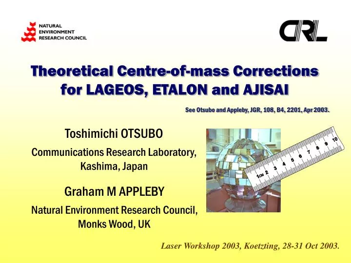
Theoretical Centre-of-mass Corrections for LAGEOS, ETALON and AJISAI. See Otsubo and Appleby, JGR, 108, B4, 2201, Apr 2003. Toshimichi OTSUBO Communications Research Laboratory, Kashima, Japan Graham M APPLEBY Natural Environment Research Council, Monks Wood, UK.

E N D
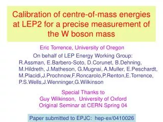
Theoretical Centre-of-mass Corrections for LAGEOS, ETALON and AJISAI See Otsubo and Appleby, JGR, 108, B4, 2201, Apr 2003. Toshimichi OTSUBO Communications Research Laboratory, Kashima, Japan Graham M APPLEBY Natural Environment Research Council, Monks Wood, UK Laser Workshop 2003, Koetzting, 28-31 Oct 2003.
Satellite signature effect • Multiple reflectors contributing to the satellite response. • System-dependent detection timing. • Single photon • C-SPAD • MCP-PMT • Key error factor to achieve accurate GM and TRF scale.
ETALON(1&2) USSR 1989 Altitude 19000 km Diameter 1.294 m 2134 CCRs AJISAI Japan 1986 Altitude 1500 km Diameter 2.15 m 1436 CCRs LAGEOS(1&2) US+Italy 1976, 92 Altitude 5900 km Diameter 0.60 m 426 CCRs
Response from single reflector • 3 factors to be considered. • Effective reflection area (a) • Reflectance (e) • Diffraction • How to compute the intensity. ∝ae … diffraction neglected. ∝a2e … simple diffraction model. [Neubert, 1994; Otsubo, 1999] ∝ane … this study.
← Effective reflection area Reflectance →
Centre-of-mass correction Extracted from Otsubo and Appleby, JGR, 108, B4, 2201, Apr 2003. 0.25 0.24 (m) LAGEOS n=1.1 257.6 r - nL 251 “Standard” 252 250 249 247 (n=2.0) Single Photon 245 Hx 250 2-sigma 247 2.5-sigma 245 3-sigma 242 w/o clipping C-SPAD 249 1 p.e. 245 Ideal S.P. (<0.1 p.e.) 257 100 p.e. 256 10 p.e. PMT (LEHM) 248 300 ps 244 1ns 256 1 ps 242 3ns FWHM 252 100 ps
Centre-of-mass correction Extracted from Otsubo and Appleby, JGR, 108, B4, 2201, Apr 2003. 1.00 0.95 (m) AJISAI n=1.2 1010 “Standard” 1028 r - nL 1002 993 987 977 (n=2.0) Single Photon 985 Hx 997 2-sigma 985 2.5-sigma 976 3-sigma 962 w/o clip C-SPAD 1023 100 p.e. 1020 10 p.e. 977 Ideal S.P. (<0.1 p.e.) 990 1 p.e. PMT (LEHM) 1009 300 ps 976 3 ns FWHM 1022 1 ps 1017 100 ps 993 1 ns
Centre-of-mass correction Extracted from Otsubo and Appleby, JGR, 108, B4, 2201, Apr 2003. 0.60 0.55 (m) ETALON n=1.3 613 r - nL 576 “Standard” 593 582 575 570 (n=2.0) Single Photon 565 Hx 552 w/o clip 580 2-sigma 564 2.5-sigma 556 3-sigma C-SPAD 613 100 p.e. 558 Ideal S.P. (<0.1 p.e.) 608 10 p.e. 573 1 p.e. PMT (LEHM) 598 300 ps 607 100 ps 612 1 ps 562 3 ns FWHM 578 1 ns
Discussions (personal opinions) for mm ranging • Avoid the intensity-dependent bias ON-SITE! • Likely to become the elevation-angle-dependent bias, which can significantly degrade the station height determination. • C-SPAD does NOT compensate the satellite returns. 1 cm for LAGEOS, 4-5 cm for AJISAI and ETALON. • MCP+CFD seems ok at 1-cm level, but not at 1-mm level. • Try the on-site shot-by-shot experiment. • kHz laser? Go for STRICT single photon!
Range residuals vs Intensity (Otsubo and Genba, DC Workshop, 2002)
Range residuals vs Intensity (Otsubo and Genba, DC Workshop, 2002)
Range residuals vs Intensity (Otsubo and Genba, DC Workshop, 2002)
Discussions (personal opinions) for mm analysis • Better adjust the range bias for a while. • 1-mm accuracy is still a challenge. • Impossible to model the CoM correction for multi-photon (esp. MCP+CFD) systems at 1-mm accuracy. • Many other systematic error sources. • Accept a constant offset bias. Too risky to fix it to 0 mm. • Tight constraints can be applied if necessary. • A different story when all stations do the single photon.
Summary • Stations, Eliminate any systematic range errors. • Analysts, Not assume zero range bias. • English speakers, Is the word “bias” appropriate? Probably negative impression to non-SLR people.
Satellite Signature Effect in GLONASS SLR Data Toshimichi OTSUBO Communications Research Laboratory, Kashima, Japan Graham M APPLEBY Philip GIBBS Natural Environment Research Council, Monks Wood, UK Laser Workshop 2003, Koetzting, 28-31 Oct 2003.
GLONASS CCR Array New type (except GLO-88) - 132 CCRs. - Since GLO-84. Old type - 396 CCRs. - Until GLO-80.
old Effective array size estimation - for 2001. - estimated by concerto ver 3. - bias elevation dependent average ~ (eff array size) x 0.15 . old NEW
NEW Effective array size estimation - for 2002. NEW NEW
Summary • GLONASS CCR Design Large flat array is probably not the best idea. It causes the elevation-dependent range error. ~ 2 cm on average. New CCR array at least halved the signature effect. < 1 cm on ave. • Return energy vs signature effect Difficult in observing new GLONASSes esp in daytime? What is the best array pattern for such high orbiters? How about in the GALILEO project?