Download
1 / 2
20 likes | 119 Vues
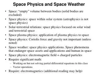
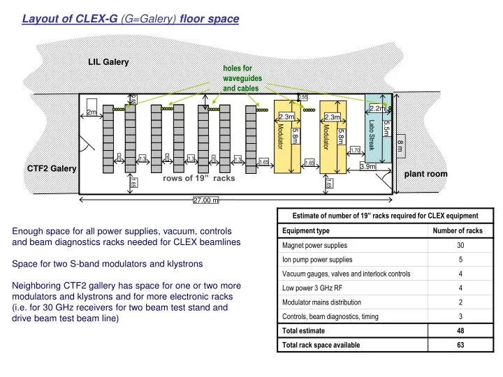
Modulator. Modulator. LIL Galery. 8 m. CTF2 Galery. plant room. 1.65. 1.65. 1.65. 1.70. 1.65. 2m. 3.9m. 5.5m. Labo Streak. 2.3m. 2.3m. 0.85. 0.55. 5.8m. 5.8m. 1.3. 1.3. 1.3. 1. 1. 1. 2.2m. Layout of CLEX-G (G=Galery) floor space. holes for waveguides and cables.

E N D
Modulator Modulator LIL Galery 8 m CTF2 Galery plant room 1.65 1.65 1.65 1.70 1.65 2m 3.9m 5.5m Labo Streak 2.3m 2.3m 0.85 0.55 5.8m 5.8m 1.3 1.3 1.3 1 1 1 2.2m Layout of CLEX-G (G=Galery) floor space holes for waveguides and cables rows of 19” racks 27.00 m Enough space for all power supplies, vacuum, controls and beam diagnostics racks needed for CLEX beamlines Space for two S-band modulators and klystrons Neighboring CTF2 gallery has space for one or two more modulators and klystrons and for more electronic racks (i.e. for 30 GHz receivers for two beam test stand and drive beam test beam line)
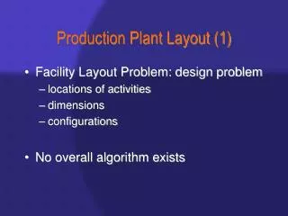
F D F D D D D D D D D D D TBL F F F F F F F D D F DUMP D F F F D D DUMP DUMP TBTS CALIFES Probe beam injector ITB DUMP D F Modulator F F F F F F F F D D D D D D D D Modulator Labo Streak LIL-ACS LIL-ACS LIL-ACS DUMP Positioning of CLEX-G relative to CLEX-A