Download
1 / 37
370 likes | 552 Vues
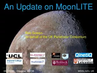
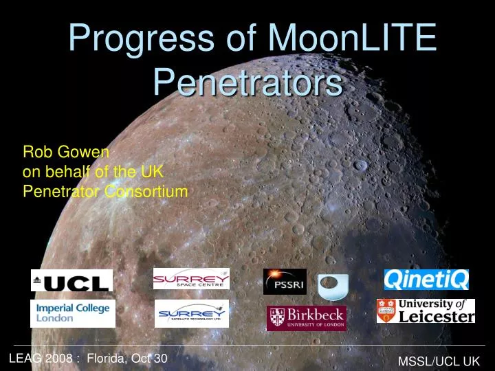
Progress of MoonLITE Penetrators. Rob Gowen on behalf of the UK Penetrator Consortium. LEAG 2008 : Florida, Oct 30. MSSL/UCL UK. Contents. Brief overview Status Phase-A elements Impact Trial Collaboration. MoonLITE Mission.

E N D
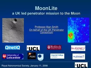
Progress of MoonLITE Penetrators Rob Gowen on behalf of the UK Penetrator Consortium LEAG 2008 : Florida, Oct 30 MSSL/UCL UK
Contents • Brief overview • Status • Phase-A elements • Impact Trial • Collaboration
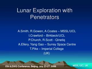
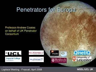
MoonLITE Mission A UK led science mission including an orbital communications package and to emplace 4 penetrators on the Moon for :- • Science:Lunar science (inc. geology, chemistry, interior structure) + water ice/volatiles in permanently shadowed craters and astrobiological connections + ground truth. • Exploration:For manned missions -> water for ISRU + sites of possibly dangerous seismic levels for lunar bases + radiation shielding effectiveness of lunar regolith. • UK plc: Showcase British Innovation • Public interest: First UK led mission for 30+ years, already much media and personal interest. • Strategic Potential: For future solar system bodies (e.g. Europa/Ganymede, Titan/Enceladus, NEOs…) Penetrators - a new tool in the toolbox for planetary exploration
Polar comms orbiter MoonLITE Mission 3 • Delivery and Comms Spacecraft(Polar Orbiter) • Emplace 4 penetrators into lunar surfaceeach 13Kg @300m/s • Landing sites:Globally spaced - far side - polar region(s) - one near an Apollo landing site for calibration • Duration: 1 year operations Far side 4 2 1
Science & Exploration Objectives lunar base ? Far side 3 • Characterize water, volatiles, and astrobiologically related material at lunar poles. => Water is key to manned missions • Constrain origin, differentiation, 3d internal structure & far side crustal thickness of moon via a seismic network. • Investigate enigmatic strong surface seismic signals => identify potentially dangerous sitesfor lunar bases • Determine thermal & compositional differences at polar regions and far side. • Obtain ground truth for remote sensing instruments 4 2 1
Feasibility & Heritage • Lunar-A and DS2 space qualified • Military have been successfully firing instrumented projectiles for many years • Most scientific instruments have space heritage DS2 (Mars) NASA 1999 ? Mars96 (Russia) failed to leave Earth orbit When asked to describe the condition of a probe that had impacted 2m of concrete at 300 m/s a UK expert described the device as ‘a bit scratched’! Japanese Lunar-A cancelled Many paper studies and ground trials
Program and Status • Late 2006 : PPARC initiated lunar mission studies • Early 2007 : MoonLITE recommended for first mission • May 2008 : Full scale impact trial at Pendine Sands, Wales. • July 2008 : MoonLITE International Peer Review. Strongly endorsed and recommended proceed to Phase-A study. • 08 Sep’08 : MoonLITESOI considered by STFC Peer Review Process – passed: now 3 part Phase-A Mission, PDS, Penetrators ‘ MoonLITE mission...inspirational...’ NASA
Proposed Development Program Objective: within 2 years to be ready to proceed to mission construction • Parallel Phase-A and Technical Development • Review at end of Phase-A • Final Review at end of technical development
PHASE-A • Penetrator Delivery System • Penetrator • baseline • - options
Penetrator Delivery System • Requirements: • Progress telemetering back to s/c • Descent imaging • Impact velocity 300m/s • Attack angle < 8degs • Separate impact site for PDS away from penetrator • Launch from spacecraft • Spin stabilise • Fire de-orbit motor • Re-orient • Separate penetrator from delivery system • impact descent sequence courtesy SSTL
aft flare • Internal bays • ease of AIT • consider plastic -> good insulation -> save power-> improvelifetime for flight stability in regolith batteries/RHU & heat switch (CofG forward) • power options: • fuel cells • micro-rtg Penetrator – post impact • Impact physics group • regolith properties • cratering • skin depth modification • Phase-A study: • impact physics • aft flare • power options • internal bay options crater few metre below surface MSSL/UCL UK LEAG 2008 : Florida, Oct 30
Penetrator – post impact crater • Phase-A study: • trailing aerial option: trailing aerial (de-risk comms through regolith & save power) comms MSSL/UCL UK LEAG 2008 : Florida, Oct 30
heat flow • (magnetometer) • accelerometers Penetrator – post impact • Phase-A study: • needle probes sub-surface 0.8m • Maximum vertical separation for gradient measurements • Baseline: needle probes • Backup: patch thermometers MSSL/UCL UK LEAG 2008 : Florida, Oct 30
Penetrator – post impact • Phase-A study: • sample imager • stand off techniques • water/volatiles • geochemistry drill (sample acquisition) • sample imager (geologic context, mineralogy) MSSL/UCL UK LEAG 2008 : Florida, Oct 30
Penetrator – post impact • micro seismometers DHU PCU MSSL/UCL UK LEAG 2008 : Florida, Oct 30
Impact Trial: 19-21 May 2008 • Full-scale • 3 Penetrators, Aluminium • 300m/s impact velocity • Normal Incidence • Dry sand target 13 Kg 0.56m … just 9 months from start to end. Starting from scratch in Sep’07
Impact trial – Payload Mass spectrometer Radiation sensor Batteries Magnetometers Accelerometers Power Interconnection Processing Micro-seismometers Accelerometers, Thermometer Batteries,Data logger Drill assembly
Impact Trial - Objectives Demonstrate survivability of penetrator shell, accelerometers and power system. Assess impact on penetrator subsystems and instruments. Determine internal acceleration environmentat different positions within penetrator. Extend predictive modelling to new impact materials and penetrator materials. Assess alternative packing methods. Assess interconnect philosophy.
Trial Hardware Inners Stack
Impact Trial - Configuration • Rocket sled • Penetrator
Target • Dry sand • 2m x2m x6m • Small front entrance aperture (polythene)
1’st Firing - Results • Firing parameters: • Impact velocity: 310 m/s • (c.f. 300m/s nominal) • Nose-up ~8degs (c.f. 0 degs nominal) • => worst case • Penetrator found in top of target • Glanced off a steel girder which radically changed its orientation. • Penetration: ~3.9m • Much ablation to nose and belly • Rear flare quite distorted. • Penetrator in one piece ✓
1st Firing – internal Results Micro seismometer bay Connecting to MSSL accelerometer and data processing bay
1’st Firing – accelerometer data (a) Front end (QinetiQ) hi-time res: 2nd peak- > body slap higher gee forces than along axis ~ 5 kgee smoothed, ~16 kgee peak high frequency components ~5khz
1st Firing - accelerometer data (b) Rear end (MSSL) 11 kgee Along axis: • Cutter impact : 3kgee • Main impact : 10kgee • Girder impact : 1kgee Along axis cutter Main impact Girder 15 kgee Vertical axis 4 kgee Lateral Axes: • ~40% more gee forces than along axis. Horizontal axis
2nd Firing “Jaws-3” ? ..struck steel girder and moved it 6 inches
Survival Table No critical failures Triple worst case: exceed 300m/s, >8deg attack angle
Impact Trial Objectives Demonstrate survivability of penetrator body, accelerometers and power system. Assess impact on penetrator subsystems and instruments. Determine internal acceleration environmentat different positions within penetrator. Extend predictive modelling to new penetrator materials,and impact materials. Assess alternative packing methods Assess interconnect philosophy.
Next Steps & Strategy … • Next full scale trial – aiming for 4th quarter ’09. • Small scale trials – de-risk full scale trials and allow more complicated scenarios (e.g. regolith layering.) • Impact into closer representative lunar regolith • Design for Moon…and eventually… • Full-up system (all operating) • Transmit from target in parallel :- - MoonLITE Phase-A
Collaboration Possibilities • Communications • Artificial Seismic event • ILN • Launch • Other
- End - Penetrator website: http://www.mssl.ucl.ac.uk/planetary/missions/Micro_Penetrators.php email:rag@mssl.ucl.ac.uk