Download
1 / 33
330 likes | 548 Vues
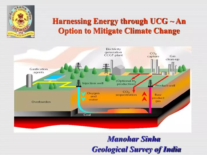
Harnessing Energy through UCG ~ An Option to Mitigate Climate Change. Manohar Sinha. Geological Survey of India. ENVIRONMENTAL BENEFIT OVER MINING AND POWER PLANT. LOW PARTICULATE EMISSIONS LOW RISK OF SURFACE WATER POLLUTION REDUCED METHANE EMISSIONS

E N D
Harnessing Energy through UCG ~ An Option to Mitigate Climate Change Manohar Sinha Geological Survey of India
ENVIRONMENTAL BENEFIT OVER MINING AND POWER PLANT • LOW PARTICULATE EMISSIONS • LOW RISK OF SURFACE WATER POLLUTION • REDUCED METHANE EMISSIONS • NO DIRT HANDLING AND DISPOSAL • NO COAL WASHING AND DISPOSAL • LESS NOISE AND VISUAL IMPACT AT SURFACE
ENVIRONMENTAL BENEFIT OVER MINING AND POWER PLANT • NO ASH HANDLING AND DISPOSAL AT PP SITE • LESS SO2 • LESS NOX • Facilitate Carbon capture • LESS TRANSPORT • NO MINE WATER RECOVERY AND SURFACE HAZARDS
ADDITIONAL BENEFITS OF UCG APPROACH • LOW OCCUPATIONAL HEALTH AND SAFETY RISKS • POTENTIALLY LOW OVERALL CAPITAL AND OPERATING COST • FLEXIBILITY OF ACCESS TO MINERAL • LARGE COAL RESOURCE EXPLOITABLE
ENVIRONMENTAL IMPACT • LEACHING OF ORGANICS FROM GASIFIER , e.g., PHENOLS • INCREASED CONC. OF INORGANIC SALTS • DISSOLVING OF HAZARDOUS GASES ~ (H2,CH4,CO2,H2S,NH3) IN GROUNDWATER • LEACHING OF HEAVY METALS ( Hg,As,Pb,Cr,Cd) • EMISSIONS OF POLLUTANTS AND GREENHOUSE GASES TO ATMOSPHERE
Criteria to be considered for potential UCG sites Physical attributes of target coal seam Chemical properties of target coal seam Structural set up Overburden characteristics Hydrological regime Land use consideration and acceptance by community
Physical attributes of target coal seam Depth ~ > 100m, preferably > 300m Thickness ~ > 2.5 m Thicknessvariation should be < 25% Permeability Desired Seam Permeability 50 – 150 md
Chemical properties of target coal seam ASH 10 to 40% [Heat value/calorific value (3.5 – 4 MJ /m3) of product gas almost constant up to 40%] ; decline steadily beyond 40% Rank & Moisture Low rank coal preferred [High in moisture and relatively more porous] Desirable moisture content < 15 wt % Caking & Swelling low caking coal [Inertinite rich; higher Caking & Swelling properties result instability of gasifier ] Reactivity Reactive components increase amount of hydrogen content in the product gas [Liptinite (exinite) has higher H/C ratio and produces large amount of gas on heating] Desirable Sulphur content < 1 wt %
Sructural set up Dipof seam Steeper seam gradient preffered Dipping bed enhances better pyrolysis ~ more gas Tars /Liquids flow down in steep dipping beds favouring effective combustion Fault Site should be away from major fault (US ~ >0.8km) Minor faults density must be < 1 within 31m (Oliver & Dana) Faults can displace target seam ~ problem for in-seam drilling Mine induced fractures must be taken care of
Overburden characteristics Preferably impervious strata in roof & floor of seam Desirable thickness just overlying seam – 15m No workable seam within 15m overburden Desirable Permeability of overburden - < 5 md Considerable mechanical strength to avoid roof collapse Resource Minimum 3.5 Mt
Hydrological regime Desirable hydraulic head > 200 m No good aquifer in the vicinity Thorough characterization of existing aquifer Careful monitoring during operations Optimal pressure in gasifier to be maintained so that gasification pressure < hydrostatic pressure Land use considerations Limited human activity ~ settlement / mine No waterways (rivers / lakes) overlying the site
Resource Scenario in India About 79 billion tonne NON-COKING COAL (34% of total resource) within depth range of 300 –1200 m. Of which 12.6 billion tonne within 600-1200m and 25.7 billion tonne of LIGNITE at > 150 m depth in East Coast Lignite field, Tamil Nadu
GONDWANA BASINS OF INDIA Singrauli Rajmahal Talcher Godavari Suitable coalfields
Geological map of East Coast lignite filed, Tamil Nadu LIGNITE OCCURENCES OF TAMIL NADU TAMIL NADU Proved areas Target Areas RAMNAD SUBBASIN Ramnad
List of coal/lignite-fields (outside Mining / CBM alloted area) warrant immediate attention Thick coal (>300m, eastern part) beyond mining Considerable thickness of overburden (Trap) Far from active mining area Rajmahal-Birbhum Persistent thickness (<300m, E. part of main basin) Free from major structural disturbance Singrauli Talchir Thick persistent coal (>300m), in central part Godavari Thick single seam (>300m), East of Kothagudem Thick forest cover, not suitable for immediate mining Ramnad Persistent lignite (>300m), beyond mining Matching physical attributes
GEOLOGICAL MAP OF RAJMAHAL COALFIELD Gopalnagar-Ganpur
Gopalnagar-Ganpur, Rajmahal Coalfield Seam No: IV Thickness: 3 - 4 m Depth: 320-360 m, Trap cover – 250-300m Dip: 20-40 Roof: immediate 2-3m thick shale / total overburden >20m Resource: 20 million tonne over 4sqkm Rank– High volatile bituminous Ash– 20 –49% , Moisture– 4 – 6 % Liptinite– 4 - 16 %, Inertinite– 22 - 44 %
Disposition of coal seams in the western part of Gopalnagar-Ganpur sector, Rajmahal-Birbhum Coalfield N 2-3m shale Roof 250-300m 320-360m Seam IV (3-4m) Seam III Seam I& II
GEOLOGICAL MAP OF TALCHER C F SCALE Jalatap Quarternary deposits Laterite Kamthi Formation Barren Measures Barakar Formation Karharbari Formation Talchir Formation Metamorphics Fault
Jalatap block, Central part of Talcher Coalfield Seam No: IX Thickness: 10 m Depth: 300-370 m Dip: 30 Roof: immediate 1m thick clay / total overburden >15m Resource: 125 million tonne over 4sqkm Rank– High volatile bituminous Ash– 15 –45% , Moisture– 2 - 13% Liptinite– 21 %, Inertinite– 26 %
Disposition of coal seams in Jalatap block, Talchir Coalfield 300-370m 1m thick Clay roof Seam IX (10m) Seam VIII
Bandha block, Singrauli Coalfield Seam No: VI Thickness: 12 - 15 m Depth: 125 - 200 m Dip: 20 - 30 Roof: Mainly sandstone >20m Resource: 235 million tonne over 4sqkm Rank– High volatile bituminous Ash– 23 –27% , Moisture– 6 - 9% Liptinite– 16 - 19%, Inertinite– 32 - 42 %
SBH-6 FENCE DIAGRAM SHOWING CORRELATION OF REGIONAL BARAKAR COALSEAMS VI AND VII IN BANDHA BLOCK, SINGRAULI COALFIELD, M.P. N SBH-1 VII 81.15 2.28 VII VI 98.43 VI 15.05 124.80 VII SBH-4 VI V 179.15 1.50 SBH-3 IV 4.96 205.68 III VII 227.90 1.08 II A VI 0.80 256.70 II 271.40 3.25 SBH-8 I 315.62 1.00 VII SBH-7 VI 415.30 SBH-2 VII VI VII VI SBH-5 VII VI INDEX Barren Measures Barakar Formation Talchir Formation VI Coal Seam Seam-VI Seam-VI 125-200m Seam-VI (12-15m) Seam-VI
Geological map of East Coast lignite filed, Tamil Nadu LIGNITE OCCURENCES OF TAMIL NADU TAMIL NADU Proved areas Target Areas RAMNAD SUBBASIN Ramnad
Tiyanur block, Ramnad sub-basin, East Coast Lignite Seam No: II Thickness: 3 - 12m Depth: 340 – 460m Dip: 20 - 30 Roof: Clay >20m Resource: 150 million tonne over 28sqkm Rank– Lignite Ash– 5 –15% , Moisture– 45% Liptinite– 2 - 10%, Inertinite– 5 - 10 %
Fence diagram showing disposition of litho - Formations and lignite seams in Tiyanur sector. N Scale 500 m 0 1000 m 200 m 400 m II (3-12m) I INDEX Quaternarysediments Cuddalore/Tittacheri Fm. Neyveli Fm. Lignite seam II
Simplicity of UCG very attractive but development of reliable working programme with acceptable cost benefit ratio seems difficult in practice Technical feasibility depends on multidisciplinary aspects thus trial must be undertaken at pilot scale For every geological set up a tailor made site specific work plan has to be designed to exploit the targeted resource
SUGGESTION Multi organizational effort and multi faceted study under an Independent Central Authority Series ofCollaborative R & D Efforts involving National Geoscientific Organizations / Coal exploration agencies ------ GSI, NGRI, CMPDI, SCCL Public / Private Oil and Coal majors (National / International) ------ ONGC, Reliance, CSIRO National Laboratories --- CIMFR R & D Institutions (National / International) ----- LLNL, CSTEP, DST, ISM
An expert committee constituted under the aegis of the Sub-Committee on Energy Minerals (Group-III of Central Geological Programming Board) for Specification of parameters (for application of UCG and Coal to Oil Technology) to be generated simultaneous with regional exploration for coal / lignite
Innovative Research and Education is warranted for wise use of non renewable resources till ‘Gestation Period’ required for other energy sources to Occupy major space of ‘Energy Basket’