Download
1 / 19
190 likes | 352 Vues
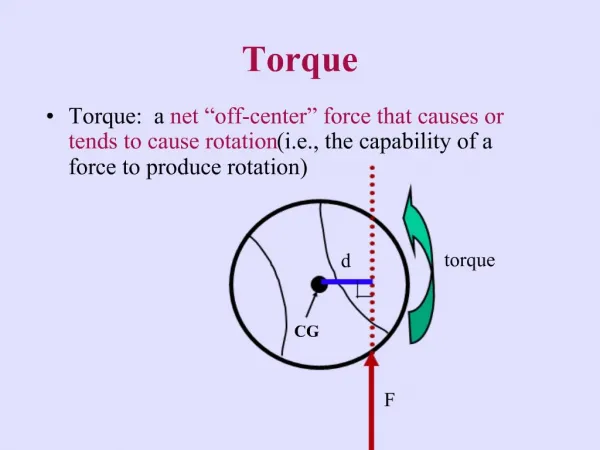
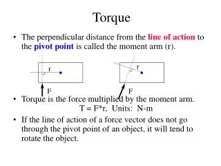
Torque. Physics 2. Prepared by Vince Zaccone For Campus Learning Assistance Services at UCSB. Torque. Torque is what causes angular acceleration (just like a force causes linear acceleration). Prepared by Vince Zaccone For Campus Learning Assistance Services at UCSB. Torque.

E N D
Torque Physics 2 Prepared by Vince Zaccone For Campus Learning Assistance Services at UCSB
Torque Torque is what causes angular acceleration (just like a force causes linear acceleration) Prepared by Vince Zaccone For Campus Learning Assistance Services at UCSB
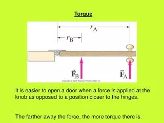
Torque Torque is what causes angular acceleration (just like a force causes linear acceleration) For a torque to be applied to an object, there needs to be a force that acts at some distance away from a pivot point. For example, consider tightening a bolt with a wrench. Which of the 3 forces shown will tighten the bolt? Pivot Point FA FC FB Prepared by Vince Zaccone For Campus Learning Assistance Services at UCSB
Torque Torque is what causes angular acceleration (just like a force causes linear acceleration) For a torque to be applied to an object, there needs to be a force that acts at some distance away from a pivot point. For example, consider tightening a bolt with a wrench. Which of the 3 forces shown will tighten the bolt? Pivot Point FA Force B will tend to rotate the bolt clockwise, which will tighten it. FC FB Prepared by Vince Zaccone For Campus Learning Assistance Services at UCSB
Torque Torque is what causes angular acceleration (just like a force causes linear acceleration) For a torque to be applied to an object, there needs to be a force that acts at some distance away from a pivot point. For example, consider tightening a bolt with a wrench. Which of the 3 forces shown will tighten the bolt? Pivot Point FA Force B will tend to rotate the bolt clockwise, which will tighten it. Notice that force A will tend to rotate the bolt counter-clockwise, loosening it. What does force C do? FC FB Prepared by Vince Zaccone For Campus Learning Assistance Services at UCSB
Torque Torque is what causes angular acceleration (just like a force causes linear acceleration) For a torque to be applied to an object, there needs to be a force that acts at some distance away from a pivot point. For example, consider tightening a bolt with a wrench. Which of the 3 forces shown will tighten the bolt? Pivot Point FA Force B will tend to rotate the bolt clockwise, which will tighten it. Notice that force A will tend to rotate the bolt counter-clockwise, loosening it. What does force C do? Force C doesn’t cause any rotation at all – there is no torque generated by force C. Why not? FC FB Prepared by Vince Zaccone For Campus Learning Assistance Services at UCSB
Torque Torque is what causes angular acceleration (just like a force causes linear acceleration) For a torque to be applied to an object, there needs to be a force that acts at some distance away from a pivot point. For example, consider tightening a bolt with a wrench. Which of the 3 forces shown will tighten the bolt? Pivot Point FA Force B will tend to rotate the bolt clockwise, which will tighten it. Notice that force A will tend to rotate the bolt counter-clockwise, loosening it. What does force C do? Force C doesn’t cause any rotation at all – there is no torque generated by force C. Why not? Force C points directly at the pivot point – no torque is created in this case. FC FB Prepared by Vince Zaccone For Campus Learning Assistance Services at UCSB
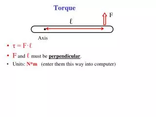
Torque Direction is perpendicular to both radius and force. The angle in the formula is between the force and the radius (from the pivot point to where the force is applied). Prepared by Vince Zaccone For Campus Learning Assistance Services at UCSB
Pivot Point FA θ r Torque Direction is perpendicular to both radius and force. The angle in the formula is between the force and the radius (from the pivot point to where the force is applied). Take a look at the diagram – r and θ are shown for force A. Prepared by Vince Zaccone For Campus Learning Assistance Services at UCSB
Pivot Point FA θ r Torque Direction is perpendicular to both radius and force. The angle in the formula is between the force and the radius (from the pivot point to where the force is applied). Take a look at the diagram – r and θ are shown for force A. • There are 2 ways to interpret the formula. • If you group the Fsin(θ) together, that represents the component of the force that is perpendicular to the radius. To get the most torque, the force should be applied perpendicular (can you see why from the formula?) Prepared by Vince Zaccone For Campus Learning Assistance Services at UCSB
Pivot Point FA θ r Torque Direction is perpendicular to both radius and force. The angle in the formula is between the force and the radius (from the pivot point to where the force is applied). Take a look at the diagram – r and θ are shown for force A. • There are 2 ways to interpret the formula. • If you group the Fsin(θ) together, that represents the component of the force that is perpendicular to the radius. To get the most torque, the force should be applied perpendicular (can you see why from the formula?) • The other option is to group the rsin(θ) together and call it the “lever arm” for the force. Think of this as the shortest distance from the pivot point to where the force is applied. This is the effective radius of the force. Again, to get maximum torque the angle should be 90°. Prepared by Vince Zaccone For Campus Learning Assistance Services at UCSB
Example: Find the torque of each force shown with respect to the pivot point at the left end of the 2m long rod. F1 is applied at the right end, and F2 is at the center. F2=30N 120° 50° F1=20N Prepared by Vince Zaccone For Campus Learning Assistance Services at UCSB
Example: Find the torque of each force shown with respect to the pivot point at the left end of the 2m long rod. F1 is applied at the right end, and F2 is at the center. F2=30N 120° 50° F1=20N The direction of this torque is into the page (use the right-hand-rule). Prepared by Vince Zaccone For Campus Learning Assistance Services at UCSB
Example: Find the torque of each force shown with respect to the pivot point at the left end of the 2m long rod. F1 is applied at the right end, and F2 is at the center. F2=30N 120° 50° F1=20N The direction of this torque is into the page (use the right-hand-rule). The direction of this torque is out of the page (use the right-hand-rule). Note that the angle could also be 60° and we get the same answer. Prepared by Vince Zaccone For Campus Learning Assistance Services at UCSB
Torque We mentioned earlier that torques produce angular accelerations. We have a formula for this relationship: This is really just Newton’s 2nd law applied to rotational motion. The moment of inertia, I, takes the place of the mass, and we use angular acceleration instead of linear. Prepared by Vince Zaccone For Campus Learning Assistance Services at UCSB
Example: Find the angular acceleration of the 2m long, uniform rod (mass=5kg) when it is subject to the 2 forces shown. F1 is applied at the right end, and F2 is at the center. F2=30N 120° 50° F1=20N Prepared by Vince Zaccone For Campus Learning Assistance Services at UCSB
Example: Find the angular acceleration of the 2m long, uniform rod (mass=5kg) when it is subject to the 2 forces shown. F1 is applied at the right end, and F2 is at the center. F2=30N 120° 50° We will need to find the moment of inertia for this rod. From our table of shapes (p.299 in textbook) we find a formula: F1=20N Prepared by Vince Zaccone For Campus Learning Assistance Services at UCSB
+ Example: Find the angular acceleration of the 2m long, uniform rod (mass=5kg) when it is subject to the 2 forces shown. F1 is applied at the right end, and F2 is at the center. F2=30N 120° 50° We will need to find the moment of inertia for this rod. From our table of shapes (p.299 in textbook) we find a formula: F1=20N Now we can apply our torque formula. We’ll define positive torque to mean “out of the page”. Alternately you can think of this as “counter-clockwise”. We can put a little arrow symbol to indicate this in the diagram. With this choice torque 1 is negative, and torque 2 is positive. Prepared by Vince Zaccone For Campus Learning Assistance Services at UCSB
+ Example: Find the angular acceleration of the 2m long, uniform rod (mass=5kg) when it is subject to the 2 forces shown. F1 is applied at the right end, and F2 is at the center. F2=30N 120° 50° We will need to find the moment of inertia for this rod. From our table of shapes (p.299 in textbook) we find a formula: F1=20N Now we can apply our torque formula. We’ll define positive torque to mean “out of the page”. Alternately you can think of this as “counter-clockwise”. We can put a little arrow symbol to indicate this in the diagram. With this choice torque 1 is negative, and torque 2 is positive. The negative sign means that the angular acceleration vector points into the page, and the object’s will accelerate in the clockwise direction. Prepared by Vince Zaccone For Campus Learning Assistance Services at UCSB