Download
1 / 24
260 likes | 277 Vues
LNG Basics for Petroleum Engineers. Michael Choi. Retired. 1. Primary funding is provided by The SPE Foundation through member donations and a contribution from Offshore Europe The Society is grateful to those companies that allow their professionals to serve as lecturers

E N D
LNG Basicsfor Petroleum Engineers Michael Choi Retired 1
Primary funding is provided by The SPE Foundation through member donations and a contribution from Offshore Europe The Society is grateful to those companies that allow their professionals to serve as lecturers Additional support provided by AIME Society of Petroleum Engineers Distinguished Lecturer Program www.spe.org/dl 2
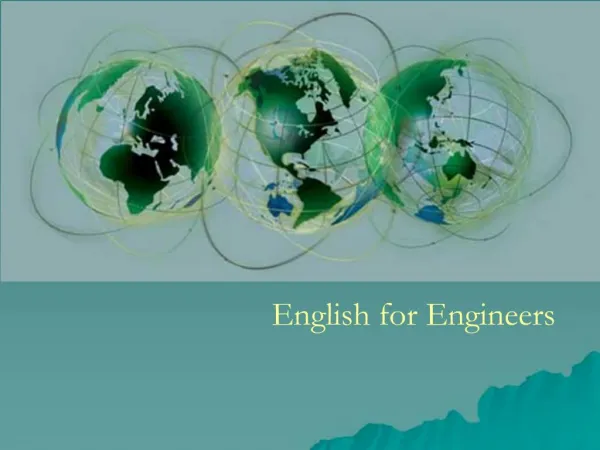
Present an Overview of LNG Plant • Why LNG? • Pre-Treatment Required • Typical Multi-Trains Plant • Natural Gas Liquefaction Thermodynamics • Commercial Liquefaction Processes • Equipment for Liquefaction • Unique Auxiliary Facilities • Novel Plant Concepts • Concluding Remarks Oman LNG Plant 3
Stranded Gas Looking for Markets • LNG Proved to be Most Economic for Distances >1,500 Mile • Volume Reduction of 600:1 • Transported in Insulated Tankers @ -162C & 1 atm. Supply Demand 4
Big Refrigeration System • Compressor/Driver • Refrigerant Condenser • Evaporator (Process Heat Exchanger) LNG Process & Equipment ? Similar to the AC System in Our Home! 5
Typical 2-Train LNG Plant Make-Up Fuel Fuel Gas Gathering Train 1 Gas Inlet Gas Treating Inlet Gas Reception NGL Recovery Liquefaction LNG Storage LNG 1.5 Bcfd Liquid 8 Mtpa (1.1 Bcfd) NGL Fractionation Train 2 Propane Propane Storage Condensate Stabilization .73 Mtpa (27 Mbpd) Butane Storage Butane .5 Mtpa (17 Mbpd) Condensate Condensate Storage 1.2 Mtpa (34 Mbpd) 6
Typical 2-Train LNG Plant Make-Up Fuel Fuel Gas Gathering Train 1 Gas Inlet Gas Treating Inlet Gas Reception NGL Recovery Liquefaction LNG Storage LNG 1.7 Bcfd Liquid 9 Mtpa (1.2 Bcfd) NGL Fractionation Train 2 Propane Propane Storage Condensate Stabilization .73 Mtpa (27 Mbpd) Butane Storage Butane .5 Mtpa (17 Mbpd) Condensate Condensate Storage 1.2 Mtpa (34 Mbpd) Inlet Gas Reception • Pipeline Manifold • Pig Receivers • Inlet Separator • Slug Catcher NGL Recovery • Scrub Column/KO after C3 Pre-Cool • Primarily C4+ to Prevent Freezing • LNG Heat Value Important for US & European Markets • 1,070 btu/scf Max • Need Turbo-Expander for High C3+ Removal Inlet Gas Treating • Amine for CO2 & H2S Removal • <50 ppm & < 4 ppm • Sulfur Recovery Unit if H2S • Mol Sieve Dehydration* • < 100 ppb • Mercury Vapor Removal* • Activated Carbon Adsorber NGL Fractionation • Deethanizer • Vapor Compression • Depropanizer & Treating • 95% & 200 psig VP • <.5ppm H2S & <15ppm S • Debutanizer & Treating • 95% & 70 psig VP @100F • <.5ppm H2S & <15ppm S Condensate Stabilization • Multi-Stage Column • Vapor Compressor • 10-12 psia RVP • De-Odorized 7
180,000 M3 LNG Tank • Full-Containment Tank to Reduce Impound Area & Improve Safety • Approx. 75M Dia x 40M H • Insulated for <.05%/D of Boil-off • Top Entry In-Tank Pumps • Total Capacity Based on Tanker Size (135,000 M3) • Plus 4+ Days Production 8
Inside the Tanks Single-Stage Multi-Stage Tank with Pump Caissons 9
LNG Loading System • 16” Chiksan Type • 3+1 – LNG Arms • 3,500 M3/Hr/Ea. • 10,500 M3/Hr • 140K M3 Tanker • 4+1 – Systems • 14,000 M3/Hr • Qmax & Qflex • 200K+ M3 • 1 – Vapor Return 10
Methane or Nitrogen Air/Water Ethylene Propane Cost of Refrigeration Cost/Btu Removed -162C 25C Temperature 11
Min. DT Natural Gas Liquefaction Processes 25C Gas Cooling Condensation Temperature Liquid Sub-cooling -162C H (Enthalpy - Heat Removed) 12
Propane Propane Propane Propane 80F 80F Refrig Refrig Refrig Refrig . . . . 1st Stage 1st Stage 1st Stage 1st Stage CoP Optimized CoP Optimized CoP Optimized 2nd Stage 2nd Stage 2nd Stage 2nd Stage Cascade Refrigerant Cycle Cascade Refrigerant Cycle Cascade Refrigerant Cycle 3th Stage 3th Stage 3th Stage 3th Stage Temperature Temperature 1st Stage 1st Stage 1st Stage Ethylene Refrig 2nd Stage 2nd Stage 2nd Stage 1st Stage 2nd Stage . . . Methane Refrig. - - 260F 260F 3th Stage D D ( ( H H Enthalpy Enthalpy - - Heat Removed) Heat Removed) Cascade LNG Process • Most Straight Forward of All Processes • Kenai Plant Continuous Operation 1969 • CoP License, Plant Build by Bechtel Kenai, Alaska 13
C3 Precooled – Mixed Refrigerant Process • Most Widely Used Licensed by APCI • 1st Plant in Algeria Operating Since 1972 • Plants Built by KBR, Chiyoda, JGC, FW QatarGas LNG Plant 14
APCI AP-X Process • Largest Train Capacity @ 8 Mtpa • Overcome Spiral Wound MCHE Limit • First Unit Started in 2009 (QG-II) • No Plants Outside of Qatar APCI Supplies • Process Design • Cold Boxes • Spiral Wound Exchanger • Turbo-Expanders 15
All Processes Use Similar Equipment GE MS7001 FB Gas Turbine • Most New Plants Use Large Gas Turbine (& Combined Cycle) to Drive Refrigerant Compressors • Some Older & Smaller Trains Have Steam Turbine Drives • Many Peak Shaving Plants on Electric Drives • Use Large Process Type Centrifugal Compressors • Main Difference is in the Cryogenic Heat Exchangers 16
Main Cryogenic Heat Exchanger Use by Mixed Refrigerant Process • Air Products & Chemicals • & Linde: Spiral Wound Ex. • Max. Diameter: 5,030mm • Height: ~55m • Stainless Steel Core • 25mm Aluminum Tubing • Externally Insulated • Chill & Liquefy Gas • From –34ºC to –152ºC • At 55 to 69 Barg 17
APCI’s MR Main Cryogenic Heat Exchanger (MCHE) Spiral Wound Design 18
Heat Exchanger for Cascade Process Plate Fin Exchanger • Many Manufacturers • Use Extensively in Air Separation • Cascade & Other LNG Processes Cold Box Configuration 19
Advances in LNG Plants Onshore Conventional Design Near-shore GBS Design Offshore Steel or Concrete Floater 20
FLNG is about to be Reality Shell Prelude • Floated out of dry dock in Dec. 2013 • 3.6 mtpa of LNG capacity • Start-up expected in 2016 Petronas Kanowit • EPC in progress • 1.2 mtpa of LNG Capacity • Scheduled for deployment in 2015 ?
Conclusions • LNG Liquefaction Process Same as AC System in Our Home • Pre-Treatment Facilities Can Dwarf Liquefaction System • Mole Sieve Dehydration & Mercury Removal Required • Gas Treating & NGL Extraction May be Needed • Stabilized Condensate & Fractionated NGL Add Value • LNG Exchangers, Storage & Loading Systems Are Unique • Commercial Liquefaction Processes Well Proven, Robust & Can be Optimized for Plant Size, Gas Composition, Sales & Commercial Needs • Novel Near-Shore & Offshore Floating Concepts Are Developed 22
LNG ? 23
Your Feedback is Important Enter your section in the DL Evaluation Contest by completing the evaluation form for this presentation Visit SPE.org/dl Society of Petroleum Engineers Distinguished Lecturer Program www.spe.org/dl 24