Download
1 / 157
1.75k likes | 2.33k Vues
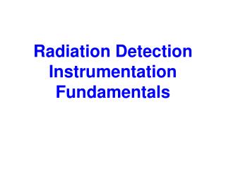
Radiation Detection Instrumentation Fundamentals. Radiation Detection Instrumentation Fundamentals. Includes Basic operation principles of different types of radiation detectors; Physical processes underlying the principles of operation of these devices, and

E N D
Radiation Detection Instrumentation Fundamentals • Includes • Basic operation principles of different types of radiation detectors; • Physical processes underlying the principles of operation of these devices, and • Comparing and selecting instrumentation best suited for different applications.
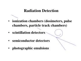
Outline • Gas-Filled Detectors • Scintillation Detectors • Solid State Detectors • Others
Gas-Filled Detectors - Components • Variable voltage source • Gas-filled counting chamber • Two coaxial electrodes well insulated from each other • Electron-pairs • produced by radiation in fill gas • move under influence of electric field • produce measurable current on electrodes, or • transformed into pulse
A Gas- Filled Detectors - one example wall fill gas Output Anode (+) End window Or wall Cathode (-) or R
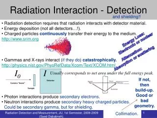
Indirect Ionization Process wall e - e - e - e - e - e - e - e - Incident gamma photon
Direct Ionization Process wall beta (β-) e - e - e - e - e - e - e - e - Incident charged particle
+ + Competing Processes - recombination Output e - e - R
Voltage versus Ions Collected Recom- bination region Ionization region Number of Ion Pairs collected Saturation Voltage 100 % of initial ions are collected Voltage
Saturation Current • The point at which 100% of ions begin to be collected • All ion chambers operate at a voltage that produces a saturation current • The region over which the saturation current is produced is called the ionization region • It levels the voltage range because all charges are already collected and rate of formation is constant
Observed Output: Pulse Height • Ions collected • Number of ionizations relate to specific ionization value of radiation • Gas filled detectors operate in either • current mode • Output is an average value resulting from detection of many values • pulse mode • One pulse per particle
Pulse Height Variation Alpha Particles Pulse Height Beta Particles Gamma Photons Detector Voltage
Ionization Region Recap • Pulse size depends on # ions produced in detector. • No multiplication of ions due to secondary ionization (gas amplification is unity) • Voltage produced (V) = Q/C • Where • Q is total charge collected • C is capacitance of the ion chanber
Ionization Chambers, continued • Chamber’s construction determines is operating characteristics • Physical size, geometry, and materials define its ability to maintain a charge • Operates at a specific voltage • When operating, the charge collected due to ionizing events is Q = CΔV
Ionization Chambers, continued • The number of ions (N) collected can be obtained once the charge is determined: N = Q / k • Where k is a conversion factor • (1.6 x 10⁻¹⁹C/e)
Other Aspects of Gas-Filled Detectors • Accuracy of measurement • Detector Walls composed of air equivalent material or • tissue equivalent • Wall thickness • must allow radiation to enter/ cause interactions • alpha radiation requires thin wall (allowed to pass) • gammas require thicker walls (interactions needed) • Sensitivity • Air or Fill gas Pressure • see next graph
Current vs. Voltage for Fill Gases in a Cylindrical Ion Chamber Air at high pressure 100 Helium at high pressure Relative Current (%) 10 Air at low pressure 1.0 Helium at low pressure 0.1 Applied Voltage (volts)
Correcting Ion Chambers for T, P • Ion chambers operate in pressurized mode which varies with ambient conditions • Detector current (I) and exposure rate X are functions of gas temperature and pressure as well as physical size of detector.
Correcting Ion Chambers for T, P • Detector current (I) and exposure rate (X) related by: • k, conversion factor • ρ detector gas density • V detector volume • STP standard temp and pressure (273K, 760 torr (1 atm)
Operating Regions of Gas-Filled Detectors Proportional Region Pulse Height Ionization Region Continuous Discharge Region Recombination Region Limited Proportional Region Geiger-Mueller Region Voltage
Values of k, Conversion Factor • Calculated as • (2.58 x 10- 4C/kg-R)(1 h / 3600 s)( 1 A s / C) • Yields 7.17 x 10- 8 A-h/R-kg
Operates at higher voltage than ionization chamber Initial electrons produced by ionization are accelerated with enough speed to cause additional ionizations cause additional free electrons produces more electrons than initial event Process is termed: gas amplification Proportional Counters
Pulse-Height Versus Voltage Ionization Region Proportional Region Recombination Region Pulse Height Voltage
Distinguishing Alpha & Beta • Proportional counters • can distinguish between different radiation types • specifically alpha and beta-gamma • Differential detection capability • due to size of pulses produced by initial ionizing events • requires voltage setting in range of 900 to 1,300 volts • alpha pulses above discriminator • beta/gamma pulses too small
Alpha & Beta-Gamma Plateau Ionization Current Beta-Gamma Plateau Alpha Plateau Detector Voltage
Gas Flow Proportional Counters • Common type of proportional counter • Fixed radiation detection instrument used in counting rooms • Windowed or windowless • Both employ 2 geometry • essentially all radiation emitted from the surface of the source enters active volume of detector • Windowless • used for alpha detection
Gas-Flow Proportional Counter Fill gas outlet Fill gas inlet anode (window- optional) Detector O-ring sample Sample planchet
Gas Flow Proportional, continued • Fill gas • selected to enhance gas multiplication • no appreciable electron attachment • most common is P-10 (90% Argon and 10% methane)
Geiger Mueller Detectors • Operate at voltages above proportional detectors • Each primary ionization • produces a complete avalanche of ions throughout the detector volume • called a Townsend Avalanche • continues until maximum number of ion pairs are produced • avalanche may be propagated by photoelectrons • quenching is used to prevent process
Geiger Mueller Detectors, continued • No proportional relationship between energy of incident radiation and number of ionizations detected • A level pulse height occurs throughout the entire voltage range
Advantages/Disadvantages of Gas-Filled Detectors • Ion Chamber: simple, accurate, wide range, sensitivity is function of chamber size, no dead time • Proportional Counter: discriminate hi/lo LET, higher sensitivity than ion chamber • GM Tube: cheap, little/no amplification, thin window for low energy; limited life
Points to Remember for Gas-filled Detectors • Know operating principles of your detector • Contamination only? • High range? • Alpha / beta detection? • Dose rate? • Alpha/beta shield?
Points to Remember for Gas-filled Detectors • Power supply requirements • Stable? • Batteries ok? • Temperature, pressure correction requirements • Calibration • Frequency • Nuclides
Issues with Gas Filled Detectors: Dead Time • Minimum time at which detector recovers enough to start another avalanche (pulse) • The dead time may be set by: • limiting processes in the detector, or • associated electronics • “Dead time losses” • can become severe in high counting rates • corrections must be made to measurements • Term is used loosely - beware!
Issues with Gas Filled Detectors: Recovery Time • Time interval between dead time and full recovery • Recovery Time = Resolving time- dead time
Issues with Gas Filled Detectors: Resolving Time • Minimum time interval that must elapse after detection of an ionizing particle before a second particle can be detected.
Correcting for Dead Time • For some systems (GMs) dead time may be large. • A correction to the observed count rate can be calculated as: • Where • T is the resolving time • R0 is the observed count rate and • RC is the corrected count rate
Relationship among dead time, recovery time, and resolving time 0 100 200 300 400 500 Pulse Height Dead Time Recovery time Resolving time Time, microseconds
Geiger Tube as Exposure Meter • “Exposure” is the parameter measuring the ionization of air. • Geiger tube measures ionization pulses per second - a “count rate”. • The number of ionizations in the Geiger tube is a constant for a particular energy but is energy dependent.
COMPENSATED GEIGER DOSE RATE METERS • GMs have a high sensitivity but are very dependent upon the energy of photon radiations. • The next graph illustrates the relative response (R) of a typical GM vs photon energy (E). • At about 60 keV the response reaches a maximum which may be thirty times higher than the detector’s response at other radiation energies.
Energy Response of GM – Uncompensated R 20 1.2 1.0 0.8 10 100 1000 E, keV
COMPENSATED GEIGER DOSE RATE METERS • Detector’s poor energy response may be corrected by adding a compensation sheath • Thin layers of metal are constructed around the GM to attenuate the lower photon energies, where the fluence per unit dose rate is high, to a higher degree than the higher energies. • The modified or compensated response, shown as a dashed line on the next graph, may be independent of energy within ± 20% over the range 50 keV to 1.25 MeV. • Compensation sheaths also influence an instrument’s directional (polar) response and prevent beta and very low energy photon radiations from reaching the Geiger tube.
R 20 1.2 1.0 0.8 10 100 1000 E, keV Energy Response of GM – Uncompensated and Compensated
Example of Compensated GM RadEye component
RadEye • Pocket meter • low power components • automatic self checks • essential functions accessed while wearing protective gloves. • Alarm-LED can be seen while the instrument is worn in a belt-holster. • Instrument also equipped with a built in vibrator and an earphone-output for silent alarming or use in very noisy environment. • Number of optional components
RadEye • Options • RadEye PRD - High Sensitivity Personal Radiation Detector • The RadEye PRD is 5000 - 100000 times more sensitive than typical electronic dosimeter. • The RadEye PRD uses Natural Background Rejection (NBR) technology. It is the only instrument of its type and size to achieve this. • Probably a plastic scintillator – more about this later