Download

1 / 99
2.54k likes | 4.46k Vues
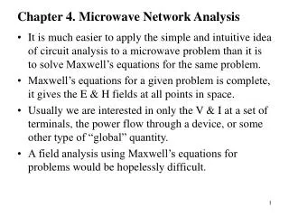
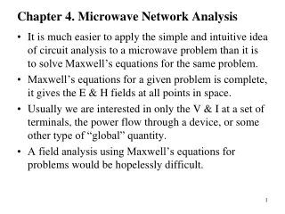
CHAPTER 5 MICROWAVE ANTENNA. MICROWAVE ANTENNA. Definition A conductor or group of conductors used either for radiating electromagnetic energy into space or for collecting it from space. or

E N D
MICROWAVE ANTENNA Definition A conductor or group of conductors used either for radiating electromagnetic energy into spaceor forcollectingit from space. or Is a structure which may be described as a metallic object, often a wire or a collection of wires through specific design capable of converting high frequency current into EM wave and transmit it into free space at light velocity with high power (kW) besides receiving EM wave from free space and convert it into high frequency current at much lower power (mW).
Basic operation of transmit and receive antennas • Electrical energy from the transmitter is converted into electromagnetic energy by the antenna and radiated into space. • On the receiving end, electromagnetic energy is converted into electrical energy by the antenna and fed into the receiver Figure 5.1 : Basic operation of transmit and receive antennas
Basic operation of transmit and receive antennas (cont) • Transmission - radiates electromagnetic energy into space • Reception - collects electromagnetic energy from space • In two-way communication, the same antenna can be used for transmission and reception. • Short wavelength produced by high frequency microwave, allows the usage of highly directive antenna. For long distant signal transmission, the usage of antenna at microwave frequency is more economical. Usage of waveguide is suitable for short distant signal transmission.
FUNCTION OF ANTENNA • Transmit energy with high efficiency . • Receive energy as low as mW. • Provide matching between transmitter and free space and between free space and receiver, thus maximum power transfer is achieve besides preventing the occurrence of reflection. • Directs radiation toward and suppresses radiation • Two common features exist at the antenna Tx and Rx antenna is the radiation pattern and impedance, but it is different in terms of transmission power and reception power. • Figure 5.2 below, shows the energy transmitted into free space via an open ended λ/4 transmission line. The proportion of wave escaping the system is very small due
FUNCTION OF ANTENNA (cont) • Mismatch exist that is surrounding space as load. • Since the two wires are closed together and in opposite direction (180°), therefore it is apparent that the radiation from one tip will cancelled that from the other. • Figure 5.2 below, shows the energy transmitted into free space via an open ended λ/4 transmission line. The proportion of wave escaping the system is very small due Figure 5.2
TYPES OF MICROWAVE ANTENNA • Horn / aperture antenna • Parabolic / dish antenna • Dipole antenna • Slotted (leaky-wave) antenna • Dielectric lens antenna • Printed (patch or microstrip) antenna • Phase Array antenna
A - HORN / APERTURE ANTENNA • Like parabolic reflectors, HORN RADIATORS can use to obtain directive radiation at microwave frequencies • Horn radiators are used with waveguides because they serve both as an impedance-matching device and as a directional radiator. Horn radiators may be fed by coaxial and other types of lines Figure 5.3 : Horn antenna
Horn Antenna • Horn radiators are constructed in a variety of shapes, as illustrated in figure 5.4 • The shape of the horn determines the shape of the field pattern. The ratio of the horn length to the size of its mouth determines the beam angle and directivity. In general, the larger the mouth of the horn, the more directive is the field pattern. Figure 5.4 : Horn radiator
THREE TYPES OF HORN ANTENNA • Horn antenna tapered / flared in one dimension only i.e in E-plane or H-plane (known as sectoral horn). • Horn antenna tapered / flared in two dimension i.e in E-plane and H-plane (known as pyramidal horn). • Conical taper / flares uniformly in all direction i.e in circular form.
THE DIFFERENCES BETWEEN THE E-, H-PLANE & PYRAMIDAL HORN SECTORAL ANTENNA
B- PARABOLIC (REFLECTOR / DISH) ANTENNA • Is a big dish like structure made from metal or wire mesh / grid. • Mesh hole ≤ λ / 12. • Widely used in microwave propagation via free space. • Also known as secondary antenna since it depends on primary antenna which acts as a feeder at the focal point (horn antenna or dipole antenna) to enhance the performance quality of the transmitter and the receiver
Introduction of parabolic antenna • A parabolic antenna is a high-gain reflector antenna used for radio, television and data communications, and also for radiolocation (radar), on the UHF and SHF parts of the electromagnetic spectrum • With the advent of TVRO and DBS satellite television, the parabolic antenna became a ubiquitous feature of urban, suburban, and even rural landscapes. Figure 5.5 : Parabolic Antenna
Why is it used? • At higher microwave frequencies the physical size of the antenna becomes much smaller which in turn reduces the gain and directivity of the antenna • The desired directivity can be achieved using suitably shaped parabolic reflector behind the main antenna which is known as primary antenna or feed .
Working rules • A parabolic reflector follows the principle of geometrical optics. • When parallel rays of light incident on the reflector they will converge at focus or when a point source of light is kept at focus after reflection by the reflector they form a parallel beam of rays
Basic Parabolic • The basic paraboloid reflector used to produce different beam shapes required by special applications. The basic characteristics of the most commonly used paraboloids are presented as below:
TRUNCATED PARABOLOID • Since the reflector is parabolic in the horizontal plane, the energy is focused into a narrow beam. With the reflector TRUNCATED (cut) so that it is shortened vertically, the beam spreads out vertically instead of being focused. This fan-shaped beam is used in radar detection applications for the accurate determination of bearing. Since the beam is spread vertically, it will detect aircraft at different altitudes without changing the tilt of the antenna. The truncated paraboloid also works well for surface search radar applications to compensate for the pitch and roll of the ship • Truncated paraboloid may be used in target height-finding systems if the reflector is rotated 90 degrees, as shown in figure 3-5B. Since the reflector is now parabolic in the vertical plane, the energy is focused vertically into a narrow beam. If the reflector is truncated, or cut, so that it is shortened horizontally, the beam will spread out horizontally instead of being focused. Such a fan-shaped beam is used to accurately determine elevation
ORANGE-PEEL PARABOLOID • A section of a complete circular paraboloid, often called an ORANGE-PEEL REFLECTOR because of its orange-peel shape. Since the reflector is narrow in the horizontal plane and wide in the vertical plane, it produces a beam that is wide in the horizontal plane and narrow in the vertical plane. In shape, the beam resembles a huge beaver tail. The microwave energy is sent into the parabolic reflector by a horn radiator (not shown) which is fed by a waveguide. The horn radiation pattern covers nearly the entire shape of the reflector, so almost all of the microwave energy strikes the reflector and very little escapes at the sides. Antenna systems which use orange-peel paraboloids are often used in height-finding equipment. Corner reflector Orange-peel paraboloid Cylindrical paraboloid
CYLINDRICAL PARABOLOID • When a beam of radiated energy that is noticeably wider in one cross-sectional dimension than in another is desired, a cylindrical paraboloidal section which approximates a rectangle can be used. A PARABOLIC CYLINDER has a parabolic cross section in just one dimension which causes the reflector to be directive in one plane only. The cylindrical paraboloid reflector is fed either by a linear array of dipoles, a slit in the side of a waveguide, or by a thin waveguide radiator. It also has a series of focal points forming a straight line rather than a single focal point. Placing the radiator, or radiators, along this focal line produces a directed beam of energy. As the width of the parabolic section is changed, different beam shapes are obtained. You may see this type of antenna system used in search radar systems and in ground control approach (gca) radar systems.
CORNER REFLECTOR • The CORNER-REFLECTOR ANTENNA consists of two flat conducting sheets that meet at an angle to form a corner, as shown in figure 5.6. The corner reflector is normally driven by a HALF-WAVE RADIATOR located on a line which bisects the angle formed by the sheet reflectors. Figure 5.6 : Parabolic reflector radiation.
CORNER REFLECTOR (cont) • A microwave source is placed at focal point F. The field leaves this antenna as a spherical wavefront. As each part of the wavefront reaches the reflecting surface, it is phase-shifted 180 degrees. Each part is then sent outward at an angle that results in all parts of the field traveling in parallel paths. Because of the special shape of a parabolic surface, all paths from F to the reflector and back to line XY are the same length. Therefore, when the parts of the field are reflected from the parabolic surface, they travel to line XY in the same amount of time.
CORNER REFLECTOR (cont) • A point-radiation source is placed at the focal point F. The field leaves this antenna with a spherical wavefront. As each part of the wavefront moving toward the reflector reaches the reflecting surface, it is shifted 180 degrees in phase and sent outward at angles that cause all parts of the field to travel in parallel paths. Because of the shape of a parabolic surface, all paths from F to the reflector and back to line XY are the same length. Therefore, all parts of the field arrive at line XY at the same time after reflection. • A parasitic array to direct the radiated field back to the reflector, or a feed horn pointed at the paraboloid is used to make the beam sharper and to concentrates the majority of the power in the beam. • The radiation pattern of the paraboloid contains a major lobe, which is directed along the axis of the paraboloid and several minor lobes. Very narrow beams are possible with this type of reflector.
PARABOLIC RADIATION PATTERN Figure 5.7 : Parabolic radiation pattern
PARABOLIC (REFLECTOR / DISH) ANTENNA as TRANSMITTER • The wave at the focus point will be directed to the main reflector and will be reflected parallel to the parabola axis. Thus the wave will travel at the same the and phase at A`E` (XY) line and the plane wave produce will be transmitted to the free space. • Waves are emitted from the focal point of the wall and bounced back in line with the axis of the parabola and will arrive on time and with the same phase of the line and will form the next plane waves emitted into free space
PARABOLIC (REFLECTOR / DISH) ANTENNA as RECEIVER • The plane wave received which is parallel to the parabola axis will be reflected by the main reflector to the focus point. • All received waves parallel to the axis of the parabola will be reflected by the wall to the point of convergence. • This characteristic makes the parabola antenna to possess high gain and a confined beam width. • These features causes a parabola has a high gain and width of the focused beam.
C- SLOTTED (LEAKY-WAVE) ANTENNA • Can be fabricated from a length of a waveguide. They are simple to fabricate, have low-loss (high efficiency) and radiate linear polarization with low cross-polarization. • Slotted antenna arrays used with waveguides are a popular antenna in navigation, radar and other high-frequency systems. These antennas are often used in aircraft applications because they can be made to conform to the surface on which they are mounted. The slots are typically thin (< 0.1 ʎ) and 0.5 ʎ (at the center frequency of operation).
SLOT ANTENNA What is SLOT Antenna:- A slot antenna consists of a metal surface, usually a flat plate, with a hole or slot cut out. When the plate is driven as an antenna by a driving frequency, the slot radiates electromagnetic waves in similar way to a dipole antenna. The shape and size of the slot, as well as the driving frequency, determine the radiation distribution pattern. Figure 5.8 : Slot antenna.
SLOTTED (LEAKY-WAVE) ANTENNA (CONT) • The slots on the waveguide will assumed to have a narrow width. Increasing the width increases the bandwidth (recall that a fatter antenna often has an increased bandwidth); the expense of a larger width is a higher degree of cross-polarization. The Fractional Bandwidth for thin slots can be as low as 3-5%; wide slots can have a FBW on the order of 75%. • An example of a slotted waveguide array is shown in Figure 5.9 (dimensions given by length a and width b) Figure 5.9 : slot waveguide with dimensions given by length a and width b.
SLOTTED (LEAKY-WAVE) ANTENNA (CONT) • As in the cavity-backed slot antenna, each slot could be independently fed with a voltage source across the slot. This would be very difficult to construct especially for large arrays. The waveguide is used as the transmission line to feed the elements. • The position, shape and orientation of the slots will determine how (or if) they radiate. In addition, the shape of the waveguide and frequency of operation will play a major role.
Slot antenna (cont) • EXAMPLE; • The dominant TE10 mode will be assumed to exist within the waveguide. Radiation occurs when the currents must "go around" the slots in order to continue on their desired direction. As an example, consider a narrow slot in the center of the waveguide, as shown in Figure 5.10 Figure 5.10 : example slot waveguide with dimensions given by length a and width b.
Slot antenna (cont) • In this case, the z-component of the current will not be disturbed, because the slot is thin and the z-current would not need to travel around the slot. • Hence, the x-component of the current will be responsible for the radiation. However, at this location (x=a/2), the x-component of the current density is zero - i.e. no current and therefore no radiation. As a result, slots cannot be placed in the center of the waveguide as shown in Figure 5.10. • If the slots are displaced from the centerline as shown in Figure 5.9, the x-directed current will not be zero and will need to travel around the slot. Hence, radiation will occur.
Slot antenna (cont) • If the slot is oriented as shown in Figure 3, the slot will disturb the z-component of the current density. This slot will then radiate. If this slot is displaced away from the center line, the amount of power that it radiates can be adjusted.
Slot antenna (cont) • If the slot is rotated at an angle about the centerline as shown in Figure 4, it will radiate. The power it radiates will be a function of the angle (phi) that it is rotated - specifically given by . Note that the z-component of the current is still responsible for radiation in this case. The x-component is disturbed; however the currents will have opposite magnitudes on either side of the centerline and will thus tend to cancel out the radiation
Slot antenna (cont) • The most common slotted waveguide resembles that shown in Figure 5: • The front end (the open face at the y=0 in the x-z plane) is where the antenna is fed. The far end is usually shorted (enclosed in metal). The waveguide may be excited by a short dipole (as seen on the cavity-backed slot antenna) page, or by another waveguide
Slot antenna (cont) • The waveguide itself acts as a transmission line, and the slots in the waveguide can be viewed as parallel (shunt) admittances.
Slot antenna (cont) • The end of the waveguide is terminated in a pyramid terminator to avoid line reflections. • The radiating field pattern depends on the spacing of the slots (phase relationship) and their orientation with reference to the waveguide. • A slot cut in the wall of the waveguide, transverse to the direction of the interior boundary currents ( due to the interior em wave) will couple the em energy from inside the wave guide to a radiant free-space wave. • The length of slot is cut to be a resonant one-half (ʎ/2) wavelength.
D) DIPOLE ANTENNAS TWO TYPES OF DIPOLE ANTENNAS: Half-wave (ʎ/2) dipole antenna (or Hertz antenna) Quarter-wave (ʎ /4) vertical antenna (or Marconi antenna) Maxwell equations, the strength of the radiated field is ; Є = 60 π dl I cosӨ cos w ( t – r/Vc) λr
D) DIPOLE ANTENNAS Cont. A for a free space short-dipole and the radiation pattern (polar diagram) in the vertical plane and a circular in a horizontal plane. The electric field, Є is directional in the vertical plane but is omnidirectional on the horizontal plane.
D) DIPOLE ANTENNAS Cont. Dipole antenna consists of 2 wires (ʎ/4 for its length) , the two wires are separated by a gap and their terminals are connected to the transmitter or the receiver. This type of dipoles is called half wave length dipole as the total length is ʎ / 2
D) DIPOLE ANTENNAS Cont. Dipole geometry Dipole configuration
D) DIPOLE ANTENNAS Cont. RADIATION PATTERN The dipole is an electric field antenna, means that the magnetic field is zero at the near field. The radiation pattern is like a donut cake with the maximum perpendicular to the dipole, and a null along it. The polarization is along the dipole.
D) DIPOLE ANTENNAS Cont. The 3D plot of the radiation pattern of a dipole antenna
D) DIPOLE ANTENNAS Cont. The radiation pattern for the Electric field for a folded dipole antenna
D) DIPOLE ANTENNAS Cont. The radiation pattern of the dipole all the field is electric as shown